and the overlapping between the sub-plies (also called cut-pieces).
Cylindrical plies are supported.
-
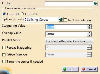
In the Entity field, select the plies to which you want to apply a 3D Multi-Splice.
- Multi-selection of entities
 is
available.
is
available. - In the multi-selection
dialog box, click
 to select entities using the Stacking Management.
- Multi-selection of entities
-
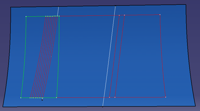
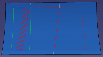
Choose the From 3D Curve selection mode:
This option allows splicing with curves lying on the ply/plies group surface. - Click
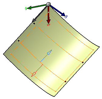
and select Line.1 and Line.2
and set the values for the Staggering Direction and the Overlap Direction as shown below.
- Curves must be selected in the right order.
-
The directions are previewed in the 3D geometry.
This is the option proposed by default.
- Click
- This option allows splicing with curves from the
flattened view of ply.
This provides the best material utilization and minimize the cross cutting of fiber on the cutpiece edge.
This is useful for Composites part made using unidirectional material for thick part (spars,…).- With this option, selected entities must share
the same flatten plane, e.g. if you select a plies group,
selection will be validated only if all the plies inside the plies group share the same flatten plane.
Otherwise, a message refusing the selection is displayed. - Once the entity selection is validated, all the
plies have the same flatten plane.
Only curves lying on that plane can be selected as splicing curves. - Parallels to selected curves will be generated on the flatten plane and the Parallel Mode field will be disabled.
- The input curve is transferred to 3D.
The new curve on 3D is used to generate the multi-splice.
Geometry transfer from 2D to 3D is based on whether unfold geometry or regular flattening is done:- If the plies have regular flattening defined
under the flatten body,
the options specified in the producibility used for creating the flattening will be applied
to 2D to 3D Geometry transfer, e.g. if flattening is created using thickness update option,
the same will be used for 2D to 3D transfer of selected splicing curve. - If the plies have unfold defined under the flatten body, options used during unfold creation will be used.
- If the plies have regular flattening defined
under the flatten body,
- If a thickness update is done:
- A straight line selected in 2D will not be a
straight line in 3D. But for manufacturing purpose,
the flatten view will be correct. - Due to tessellation during the geometry transfer
and flattening operation, when flattening a cut-piece,
there may be a deviation between the selected curve for the 2D splicing
and the contour edge of the flattened cut-piece.
- A straight line selected in 2D will not be a
straight line in 3D. But for manufacturing purpose,
- With this option, selected entities must share
the same flatten plane, e.g. if you select a plies group,
- You cannot select curves from 3D and curves from 2D at the same time.
- Starting with R21, intersecting curves are supported.

-
Optional: Select the No Extrapolation check box.
- When No Extrapolation is selected,
partial intersection is not supported. You
must select curves that fully intersect the
ply region,
otherwise the splice plies cannot be created. - When No Extrapolation is cleared, the selected curves can be extrapolated and the splice plies can be created.
- When No Extrapolation is selected,
partial intersection is not supported. You
must select curves that fully intersect the
ply region,
-
Define the Staggering Value and the Overlap Value.
-
Select a Parallel Mode:
Computation with Parallel planes otherwise geodesic has been improved in V5-6 R2021:
- In creation mode, the new computation method is used.
- If you edit multi-splices computed before V5-6 R2021, change the
Parallel Mode to another value,
then select Parallel planes otherwise geodesic again to compute the splicing with the new method.
-
If required, select the Repeat Staggering check box:
this option lets you reuse computed parallels to generate multi-splice.- Enter a repeat value.
If the repeat value is specified as N, the staggering step will be reset to 1 after staggering N steps.
For example, if there are 10 plies selected, and the repeat value is specified as 4
the first 4 plies will have the staggering step 1,2,3,4,
the plies from 6 to 8 will have the staggering step as 1,2,3,4
and plies 9 and 10 will have the staggering step as 1,2 respectively.
- Enter a repeat value.
-
If required, select the Offset Distance check box and enter an offset value.
-
If required, select the Tamp the curves if needed checkbox to optimize the shape of the cut-pieces:
All initially generated splicing curves are inspected.
Unused curves are removed, the computation formula is updated to create the next curves according
to staggering rule and splice plies correctly.- When Tamp
the curves if needed is cleared
- When Tamp
the curves if needed is selected
When the check box is selected, when splicing island plies belonging to the same sequence,
the curves used to create the cut-pieces are not staggered for each plies:
the same curves are used for all island plies in the sequence. - When Tamp
the curves if needed is cleared
-
Click OK.
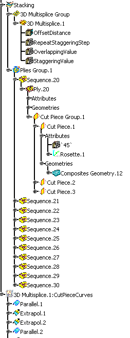
The specification tree is updated accordingly.
Multi-Splices of Multi-Splices
You can create multi-splices from existing multi-splices,
using the same operating mode.
The parameters used for the children
multi-splices can differ from the parameters used for the parent
multi-splices.
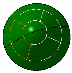
3D Multi-Splice on Cylindrical Plies
-
Click Splice Plies
 in the Splicing toolbar.
 -
In the Entity field, select the cylindrical plies on the part.
-
Click Multi-selection
at the right of the
Splicing Curves field and select the curves on the geometry.
-
Define the Staggering Value and the Overlap Value with the up and down arrows.
-
Click OK to create the splices on the cylindrical plies.
The 3D Multi-Splice feature is created and includes:
- The selected plies,
- The splicing curves,
- The staggering value,
- A staggering direction per curve,
- The overlapping value,
- An overlapping direction per curve.
Sub-plies (also called cut-pieces) are created under each ply and have the following characteristics:
-
They inherit the material and direction of the ply,
-
Their contour is associative with the father ply geometry in the following cases:
-
The ply surface is modified,
-
The ply geometry is modified e.g. the boundaries of the plies are modified or a limit contour is applied to the ply,
Note however that the number of cut-pieces is not modified during the update of the part, e.g.:
Original situation
Situation after update
Curve 2 no longer intersects the father ply geometry
The limit contour feature of cut-piece 3 will have an update error
You must delete the cut-piece manually.- They have their own rosette and producibility feature,
- They have their own geometry and can be modified individually,
- They are taken in account in the following commands:
Ply exploder
Limit contour
Multiple Core Samples
Numerical analysis
Material excess
Skin swapping
Manufacturing Document
Synchronize - They can be used for any manufacturing export,
- They can be transferred in the manufacturing model if generated in the engineering model.
-
![]()