![]()
The core samples can be edited during their creation, or after.
Once you have generated the core samples from a reference entity such as a grid, grid virtual stacking, zone group or plies group, the point location can only be modified manually.
Follow the instructions displayed when you double-click older core samples to migrate them to this new version.
Il you do not migrate them, you still can read them.
Creating Core Samples
-
Click Multiple Core Sample
 in the Analysis toolbar.
The Multiple Core Sampling dialog box opens.

-
Select the Support Surface for Core Sample.
You can select either a surface of a plies group. - Selecting a plies group reverts to selecting its associated surface.
All the plies of the plies group found along the normal to its surface will be processed. - If the selected surface is not that associated to the
plies group, points selected on this surface are processed
as follows:
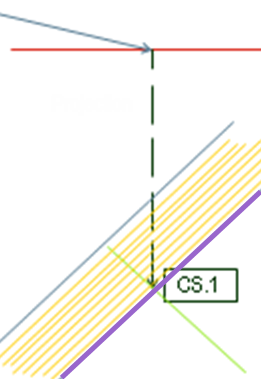
- The first plies group found is represented by the yellow lines (plies) and the purple line (its reference surface).
- The selected surface is shown in red.
- The blue arrow points to the selected point.
- The dotted green arrow shows its projection on the reference surface of the first plies group found.
- The green line is the normal to the reference surface of the plies group at the projection of the selected point.
- Multiple Core Samples processes all the
plies of that plies group along this line.
-
Optional: Select the No direct computation check box.
- No computation is done when you add points, until you click Apply.
- As a consequence, the Results table is not updated until you click Apply.
Pick points directly in the graphic area to create the core samples.
The core samples are added to the list.-
Alternatively, click Create points from Reference Entity.
Select a reference entity in the dialog box that opens. It can be: - A grid or a virtual stacking: A point is created at the center of each cell of the grid.
- A zone group: A point is created at the center of each
zone.
If the zone contains a transition zone, the point is created on the portion with no transition zone, meaning it is not the exact center. - A plies group: A point is created in each surface with a constant thickness area.
If you have selected a plies group, define the width or the areas to consider.
Either key in a value, or measure the distance between two plies using the contextual menu.Click OK.
- The core samples are created and listed under List of Core Samples, with their details.
- Associativity between the core samples and the reference entity is managed by manual edition.
- If you have selected a grid, virtual stacking or a zone group, they are listed under Reference Entity.
Under List of Core Samples, select one or several lines to edit their information.
- Index is the order of core samples. Use the green arrows to modify it.
- Name is the name of the core sample. Click a name to edit it.
- Ply is the name of the ply found under the point. It is not editable.
- Thickness is the value of the laminate found
under the point. It is not editable.
If the considered plies group insersets another one, the thickness is computed on both plies groups. In such a case, the thickness is not accurate, but still relevant. - Point is the name of the point you have picked. It is not editable.
- Hide/Show indicates the visibility status. Click either Hide or Show to change the status.
- Direction can be Normal (to the surface) or Invert. Click Invert direction in the dialog box or the arrow in the graphic area to modify it.
- Cut-Pieces, Non Struct Plies and Filters are the options selected for the core samples as you picked the points.
- Reference Entity. This column is filled with the name of the entity previously selected if you had entered a zone group, a grid or a grid virtual stacking.
- Difference.
If you select one core sample, information is displayed under Results.
Results is inactive if you select several core samples.You are ready to do one of the following.
-
Alternatively, click Edit.
-
Click Invert Direction, Hide, Show, Remove to modify the direction, the visibility status or delete the core samples.
-
Check the results (disabled if you have selected several core samples).
Under List of Plies, the details of the plies: - Number of entities
- Total thickness
- Plies group
- Sequence
- Entity
- Material
- Direction name
- Direction Value
- Rosette
Under Thickness Law, the details of the thickness law of the core sample:
- Material
- Thickness law as a number of plies and percentage for each direction
- Total number of plies for each direction, if there is more than one material.
Under Delta Comparison:
- Material
- Delta
- Details of the directions
- Status of the delta
- Status of the thickness
- Total Delta Difference
- Thickess difference between the core sample and the reference entity.
-
Optional: Select More (for export) to access export options.
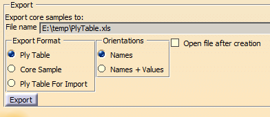
- Click ... to enter the name of the exported file.
- Select the Export Format.
- Decide if you want to export the Names, or the Names+Values of the Orientations.
- Optional: Select the Open file after creation check box.
- Click Export to create the exported file.
- Ply Table
Reference Geometry	Ply Group	 Sequence	 Ply/Insert  Material	CS.1	CS.2
Extrude.1	         PG.1	         Sequence.1	 Ply.1	     KEVLAR4		90
Extrude.1	         PG.1	         Sequence.2	 Ply.2	     KEVLAR4		-45
Extrude.1	         PG.1	         Sequence.3	 Ply.3	     KEVLAR4		0
Extrude.1	         PG.1	         Sequence.4	 Ply.4	     KEVLAR4		45
Extrude.1	         PG.1	         Sequence.5	 Ply.5	     KEVLAR4	        90
Extrude.1	         PG.1	         Sequence.6	 Ply.6	     KEVLAR4	        0
Extrude.1	         PG.1	         Sequence.7	 Ply.7	     KEVLAR4	        -45
Extrude.1	         PG.1	         Sequence.8	 Ply.8	     KEVLAR4	        45
Extrude.1	         PG.1	         Sequence.9	 Ply.9	     KEVLAR4	90	90
Extrude.1	         PG.1	         Sequence.10	Ply.10	    KEVLAR4	-45	-45
Extrude.1	         PG.1	         Sequence.11	Ply.11	    KEVLAR4	45	45
Extrude.1	         PG.1	         Sequence.12	Ply.12	    KEVLAR4	0				 0
                                             DIR	       0	    1     3
                                             DIR	       45	    1     3
                                             DIR	       -45	    1     3
                                             DIR	       90	    1     3
                                 Total Crossed Entities	        4     12
                                 Thickness	                    0.8mm	 2.4mm

Core Sample Points	        X	    Y	     Z
CS.1	   139.578205mm	       -10mm	 14.228437mm
CS.2    -92.186211mm        -10mm  17.124897mm
All plies are listed by their name. The plies with multiple intersections, if any, are listed at the end, the number of multiple intersections is given for each ply concerned. - Core Sample
Core Sample	  CS.1	   139.578205mm	       -10mm	 14.228437mm
Ply Group	 Sequence	Ply/Insert  Material	Direction  Rosette
PG.1	         Sequence.12	Ply.12	    KEVLAR4	 0	   Rosette_SP
PG.1	         Sequence.11	Ply.11	    KEVLAR4	 45	   Rosette_SP
PG.1	         Sequence.10	Ply.10	    KEVLAR4	 -45	   Rosette_SP
PG.1	         Sequence.9	 Ply.9	    KEVLAR4	 90	   Rosette_SP
              DIR	    0	   1
              DIR	    45	  1
              DIR	    -45	 1
              DIR	    90	  1
                      Total Crossed Entities	4
                      Thickness	0.8mm

Core Sample	  CS.2    -92.186211mm        -10mm  17.124897mm
Ply Group	 Sequence	Ply/Insert  Material	Direction Rosette
PG.1	         Sequence.12	Ply.12	    KEVLAR4	 0	  Rosette_SP
PG.1	         Sequence.11	Ply.11	    KEVLAR4	 45	  Rosette_SP
PG.1	         Sequence.10	Ply.10	    KEVLAR4	 -45	  Rosette_SP
PG.1	         Sequence.9	 Ply.9	    KEVLAR4	 90	  Rosette_SP
PG.1	         Sequence.8	 Ply.8	    KEVLAR4	 45	  Rosette_SP
PG.1	         Sequence.7	 Ply.7	    KEVLAR4	 -45	  Rosette_SP
PG.1	         Sequence.6	 Ply.6	    KEVLAR4	 0	  Rosette_SP
PG.1	         Sequence.5	 Ply.5	    KEVLAR4	 90	  Rosette_SP
PG.1	         Sequence.4	 Ply.4	    KEVLAR4	 45	  Rosette_SP
PG.1	         Sequence.3	 Ply.3	    KEVLAR4	 -45	  Rosette_SP
PG.1	         Sequence.2	 Ply.2	    KEVLAR4	 -45	  Rosette_SP
PG.1	         Sequence.1	 Ply.1	    KEVLAR4	 90	  Rosette_SP

              DIR	    0	   3
              DIR	    45	  3
              DIR	    -45	 3
              DIR	    90	  3
                      Total Crossed Entities	12
                      Thickness	2.4mm
The plies are listed in the order they have been processed, which makes the multiple intersections more visible, if any. - Ply Table For Import
(CPG stands for CutPieceGroup and CP for CutPiece)
PlyGroup    Sequence	 Ply	  CPG	CP	Material Direction Rosette	Surface	  Draping	Ply ID	CS.1	CS.2
PG.1	    Sequence.1	 Ply.1			KEVLAR4	 90	   Rosette_SP	Extrude.1	F	      1		         90
PG.1	    Sequence.2	 Ply.2			KEVLAR4	 -45	   Rosette_SP	Extrude.1	F	      2		         -45
PG.1	    Sequence.3	 Ply.3			KEVLAR4	 0	   Rosette_SP	Extrude.1	F	      3		         0
PG.1	    Sequence.4	 Ply.4			KEVLAR4	 45	   Rosette_SP	Extrude.1	F	      4		         45
PG.1	    Sequence.5	 Ply.5			KEVLAR4	 90	   Rosette_SP	Extrude.1	F	      5	          90
PG.1	    Sequence.6	 Ply.6			KEVLAR4	 0	   Rosette_SP	Extrude.1	F	      6	          0
PG.1	    Sequence.7	 Ply.7			KEVLAR4	 -45	   Rosette_SP	Extrude.1	F	      7	          -45
PG.1	    Sequence.8	 Ply.8			KEVLAR4	 45	   Rosette_SP	Extrude.1	F	      8	          45
PG.1	    Sequence.9	 Ply.9			KEVLAR4	 90	   Rosette_SP	Extrude.1	F	      9	     90	  90
PG.1	    Sequence.10	Ply.10			KEVLAR4	 -45	   Rosette_SP	Extrude.1	F	      10	    -45	 -45
PG.1	    Sequence.11	Ply.11			KEVLAR4	 45	   Rosette_SP	Extrude.1	F	      11	    45	  45
PG.1	    Sequence.12	Ply.12			KEVLAR4	 0	   Rosette_SP	Extrude.1	F	      12	    0			 0
                                                     DIR	   0	 1  3
                                                     DIR	   45	 1  3
                                                     DIR	   -45	 1  3
                                                     DIR	   90	 1  3
                                                            Total Crossed Entities	4   12
                                                            Thickness	0.8mm	  2.4mm

Core Sample Points	 X	    Y	   Z
CS.1	           139.578205mm	   -10mm   14.228437mm
CS.2               -92.186211mm    -10mm   17.124897mm
-
Click OK to create the core samples and exit the dialog box.
The core samples are created as CS.x under a Core Sample Group under Review Tools. -
Double-click the Core Sample Group or an individual core sample to edit them.
Editing Core Samples
-
In the Multiple Core Samples dialog box:
- Select one or several core samples under List of Core Samples and click Edit.
- Or double-click one core sample in the graphic area.
- Or double-click one or several core samples in the specification tree under a core sample group.
- Or right-click one or several core samples in the specification tree under a core sample group and select Definition in the contextual menu.
Its content varies with the selection.
The Reference Surface is the support surface selected in the main dialog box.
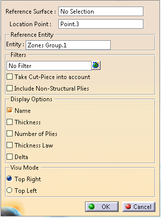
Optional: Change the location point.
This is not possible when several core samples have been selected.-
Select a Reference Entity to compare the core sample thickness law with.
- If you have created the core samples from a reference entity, this entity is proposed.
- If you have selected several core samples with the same reference entity, its name is displayed.
- If you have selected several core samples with several reference entities, Multiple CS is displayed.
-
Optional: Under Filters, click
 to select the impacted entities.
- Either select them manually.
- Or click
 in the dialog box that opens to select them with the
Stacking Management.
in the dialog box that opens to select them with the
Stacking Management.
If you have selected several core samples with the same filter, its name is displayed.
If you have selected several core samples with several filters, Multiple CS is displayed.
The Filters column is updated for this line. -
Optional: Select the Take Cut-Piece into account check box to take them into account, if any.
-
Optional: Select the Include Non-Structural Plies check box too take them into account, if any.
-
Under Display Options, select the required ones:
When you start the edition: - The information on core samples is displayed with the current options.
- An option is selected if all selected core samples share that option.
- A star before an option means several core samples have
a different status for this option.
- Select an option with a star to apply it to all selected core samples.
- Click (i.e. select and deselect) an option with a star twice to remove it from all selected core samples.
Note that Delta starts the computation of the comparison to find the delta.
The core sample information is updated in the graphic area.
If you change the composites parameters, the changes are not taken into account automatically. You need to edit the core samples and uncheck/check the box. -
Under Visu Mode, select the required option, i.e. where the information is displayed.
When you start the edition, an option is selected if it is shared by all selected core samples.
When you select an option, it is applied to all selected core samples. -
When available and required, select Show Core Sample Results to display them.
Alternatively, right-click one core sample in the specification tree under a core sample group, and select Core Sample Results in the contextual menu.
![]()