This task shows you how to create limit contours on plies or cut-pieces.
See also About
Limit Contours for more information.
You will find explanations about:
Selecting Relimited Curves
-
Open the LimitContour1.CATPart document.
-
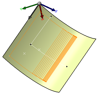
Click Limit Contour
 in the Plies toolbar.
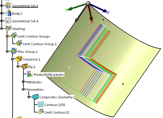
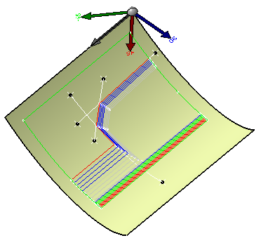
Select the entity where to insert the limit contour.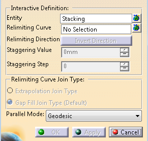
- Multi-selection of entities
 is
available.
is
available. - In the multi-selection
dialog box, click
to select entities using the
Stacking Management.
- Select a ply, a
sequence, a plies group or a
stacking.
In our example we selected Plies Group.1.
All plies must lie on the same surface.
If some plies lie on various surfaces, a warning message is issued.
- Multi-selection of entities
-
To select relimiting curves, click Multi-selection
.
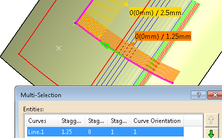
Curves must lie on the same surface as the selected entity.When you select several curves in the Multi-selection dialog box, you can edit them in one shot: you can modify the Staggering Value, the Staggering Step, the Staggering Direction, and remove curves.
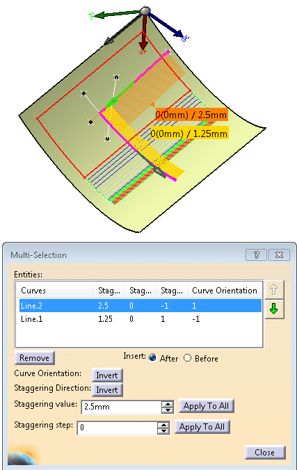
However, you cannot modify the Curve Orientation, nor reorder curves. Apply To All is not available.Select Line.2 and Line.1 in the geometry.
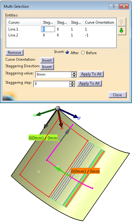
The table list the names of the curves, the Staggering Value, the Staggering Direction, the Curve Orientation.
-
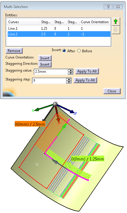
Place the cursor as shown above and enter a Staggering value of 1.25 for Line.1 and 2.5 for Line.2.
Alternatively, highlight a curve and enter the Staggering value in the box below.
You can define individual staggering value for each line, or click Apply To All to apply the same value to all curves.
Use the contextual menu to enter the Staggering value as a formula.
-
Define the Staggering Step.
By default it is set to 0. Therefore, the staggering step for the first ply will be 0, 1 for the second ply,
2 for the third ply, and so on.
-
This option is available for any Entity you have selected.
If you have selected several plies, the step is automatically defined starting from the one you selected. -
This option is influenced by the order of selection of the plies. Be careful when selecting the plies.
-
-
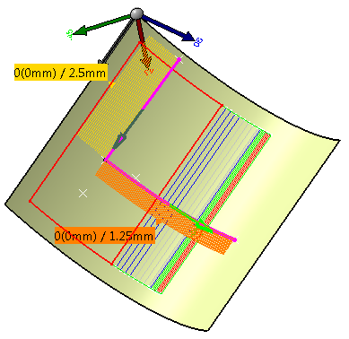
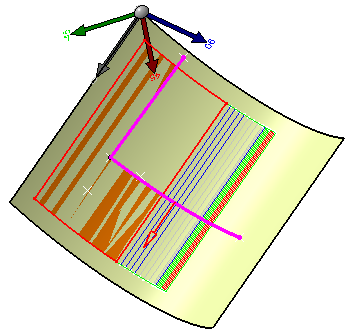
Pick a staggering to make it current.
The active staggering is shown in orange.
Note that for highly curved surfaces or large staggering value and step, a distortion could occur between the preview and the actual staggering.
Click Invert on the right of Staggering Direction, or the manipulator to invert the staggering direction.
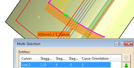
Note that the value of the Staggering Direction is now -1.
All staggerings with the same value are shown in the same color.
Multi-selection of staggering manipulators is supported. -
Pick a curve to make it current.
The orientation of the current curve is shown in green.
Click the green arrow, or Invert on the right of Curve Orientation to invert the orientation of the curve.
Notes:- The Curve Orientation is now -1.
- The curve orientation is saved in the limit contour feature.
- The
orientation of the other curve has changed too to avoid
inconsistency.
-
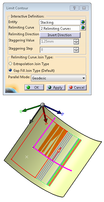
Close the Multi-selection dialog box to return to the main dialog box.
-
The relimiting direction is shown by the red arrow.
The relimiting direction is saved in the limit contour feature. -
The Limit Contour feature created is a parallel to the curve you have selected.
You can select the type of parallel that will be created:
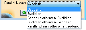
Geodesic and Euclidian impose the type you have selected.
Geodesic otherwise Euclidian will create a geodesic parallel if possible,
otherwise it will create an Euclidian parallel.
Euclidian otherwise Geodesic will create an Euclidian parallel if possible,
otherwise it will create a geodesic parallel.
Parallel planes otherwise geodesic will create an parallel planes if possible,
otherwise it will create a geodesic parallel. -
Click OK.
A Limit Contour Group node and a limit contour feature are created.
To invert it, either click the red arrow or Invert Direction in the dialog box.
Deleting Limit Contours
-
In the specification tree, right-click Ply.1.
-
Select Limit Contour object then Remove similar limit contours.
-
Select plies for which you want to remove the limit contour.
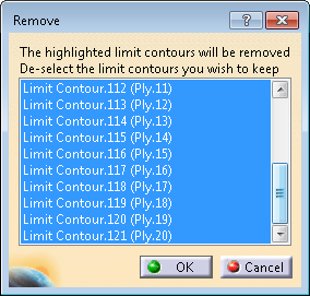
The limit contours displayed in the dialog box share the same input parameters
(i.e. curves, staggering values, staggering directions etc.). -
Select Ply.10 to Ply.20 then click OK to apply your changes.
Alternatively, select a sequence, a plies group, a stacking.
In the object contextual menu, select Remove all Limit Contours.
Using the After and Before Options
-
Open the LimitContour3.CATPart document.
-
Click Limit Contour
. -
Click Multi-selection
. -
Select Ply.1, Ply.2, Ply.3, and Ply.4 in the specification tree.
They are displayed in the multi-selection dialog box.
-
Click Multi-selection
. -
Select Line.2 and Line.1 in the geometry and set the values as shown below.
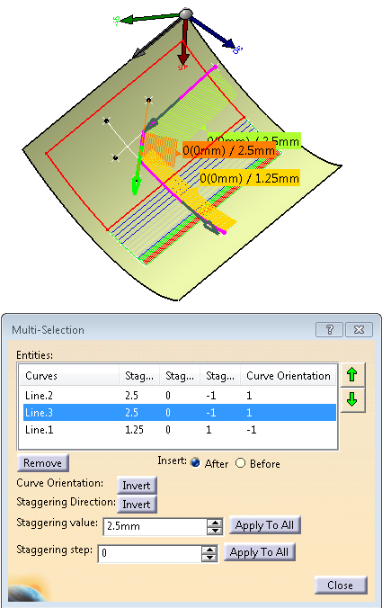
If you want to select Line.3, you must respect the order of selection of
relimiting curves for the contour to be valid.
In our example, the right order is Line.2, Line.3 and Line.1. -
Click Before, to insert Line.3 before Line.1 (or select Line.2 and click After).
-
Select Line.3 in the geometry.
-
Set the values for Line.3.
-
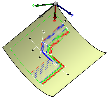
Click OK to create the limit contour.
![]()