Available in DMU Composites Review (CPR), in a CATProduct context.
In Composites Design (CPD), Composites Engineering Design (CPE) and Composites Design for Manufacturing (CPM),
the numerical analysis can be done on zones (i.e. zones groups or zones) or
on plies (i.e. stacking or plies) but you can not select a mix of zones and
plies.
Please note:
- An analysis of zones does not take cut-pieces into account.
- If you select a zones group, all the zones that it contains are analyzed.
- The result of a numerical analysis of plies can be stored in the CATPart (select the Persistent check box).
- The result of a numerical analysis of zones cannot be stored in
the CATPart (the Persistent check box and OK are
disabled).
However, this result can be exported.
In DMU Composites Review (CPR), the numerical analysis can be performed on the whole CATProduct or on a selection of CATParts under the CATProduct. However the numerical analysis result will not be stored in the CATProduct: the Persistent check box and OK are disabled.
- Part_01.CATPart from the samples\Composites directory if you are working in Composites Design (CPD), Composites Engineering Design (CPE) and Composites Design for Manufacturing (CPM).
- CPD_01.CATProduct from the samples\Composites directory if you are working in DMU Composites Review (CPR).
-
Click Numerical Analysis
 in the Analysis toolbar.
The Numerical Analysis dialog box is displayed.
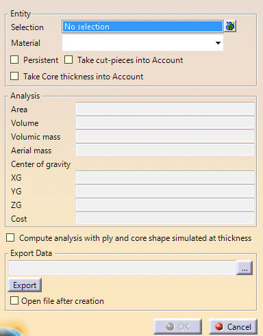
- The Persistent check box is not active when you are in DMU Composites Review (CPR).
- The Persistent and the Take cut-pieces into account check boxes are not active when you have selected zones.
-
Select the entities to be analyzed.
- Multi-selection of entities
 is
available.
is
available. - In the multi-selection
dialog box, click
 to select entities using the Stacking Management.
 - In Composites Design (CPD), Composites Engineering Design (CPE) and Composites Design for Manufacturing (CPM),
you can select
- The stacking or a portion of it,
- A zones group or a portion of it,
- Or a grid.
Be aware that ply drop along staggering is not taken into account.
- In DMU Composites Review (CPR), you can select either the
whole CATProduct
or one or several CATParts under this CATProduct.
If you select an entity under a CATPart, the CATPart itself is automatically selected.
- Multi-selection of entities
-
If necessary, select the Take cut-pieces into account check box.
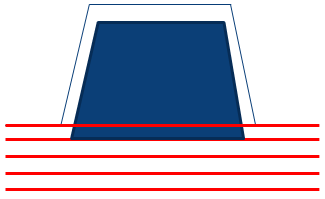
- When Take Core thickness into Account is
not selected, the computed area for plies looks like this
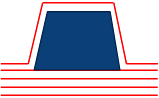
- When Take Core thickness into Account is
selected, the computed area for plies looks like this
The analysis is updated with the information concerning the cut-pieces.
You will note that the area increases due to the plies superposition.
The numerical analysis of all the plies can now be exported in an external file (.xls, .xlsx or .txt).
The default path is the path where the sample is stored. - When Take Core thickness into Account is
not selected, the computed area for plies looks like this
-
If necessary, select the Compute analysis with ply and core shape simulated at thickness check box.
Take Core thickness into Account is no longer available since it is included in Compute analysis with ply and core shape simulated at thickness.
With this option, the analysis is more time consuming but also more precise.
Messages are displayed if there are errors on plies, or if a core does not lye completely on the support surface.
- Results of this option are not persistent: you have to export them to keep them.
- If plies are defined on two overlapping support surfaces, the thickness of plies on first surface is not considered for plies lying on the second surface. In such a case, we recommend that you define all the plies on a larger single surface.
- If the top surface computed from Plies Group.1 is used to define plies from Plies Group.2, the thickness of plies added to Plies Group.1 after the computation of the top surface is not taken into consideration for the computation of plies from Plies Group.2. In such a case, we recommend that you recompute the top surface after having added plies to Plies Group.1, and that you define the plies from Plies Group.2 on the new surface.
-
Enter a storage directory and file name and click Export to export the analysis result.
An information message is displayed when data is successfully exported.
Here is the information contained in the external file:- In DMU Composites Review (CPR):

- In Composites Design (CPD), Composites Engineering Design (CPE) and Composites Design for Manufacturing (CPM):
- For zones:

- For plies:

- For a grid:

- For zones:
- In DMU Composites Review (CPR):
-
Select a Material (as defined in the Material catalog) from the list if you want to filter the results.
The data retrieved for each material enables you to create bills of material.
 |
-
Check the Persistent option if it is available and if you want the analysis to be featurized and to be displayed in the specification tree.
-
In Composites Engineering Design (CPE) and Composites Design for Manufacturing (CPM), OK is available to exit the command and store the numerical analysis under the CATPart if you have selected plies.
The Numerical Analysis element is displayed in the Stacking node under each sequence containing the selected above Material.
In DMU Composites Review (CPR), or if you have selected zones in a CATPart context, click Cancel to exit the command.
The numerical analysis result is not stored.
- You can perform a numerical analysis on a cut-piece.
- If you select Take cut-pieces into account for a ply
containing cut-pieces, the computation is made from the cut-pieces
geometries.
Otherwise, it is made from the ply geometry. - Even if Persistent is selected, no numerical analysis feature is created under each cut-piece.
- When you run a numerical analysis to find differences between two identical or similar parts (different versions of the same part, manufacturing part), a numerical inaccuracy of around 1% must be taken into account for computed areas, especially when plies have cut-out or holes. Such a difference is to be ignored.
- Since the ply drop along staggering is not taken into account, all this added mass is not taken into account. Analysis on grid only gives a rough approximation. A precise result is obtained only after ply generation.
![]()