- Skin swapping can be performed only on tangency continuous shells.
- When a Swapping feature already exists, you cannot create a second one, but you can edit it if modifications are required.
- Butt Splice Zones are taken into account by the Skin Swapping command if you select the Stacking node.
- If the Skin Swapping was applied to elements under
the staking, you can generate a Skin Swapping feature for the
Butt Splice Zones by selecting either a zone or its group.
In this case a Skin Swapping feature will be added at the end of the Composites Geometry of the corresponding elements.
-
Click Skin Swapping
 in the Manufacturing toolbar.
 -
Select the feature where you want to insert the swapping in the specification tree.
- Multi-selection of entities
 is
available.
 - In the multi-selection
dialog box, click
 to select entities using the Stacking Management.
 - Select a ply, a
sequence, a group of plies,
cut-pieces, an edge of part or a stacking.
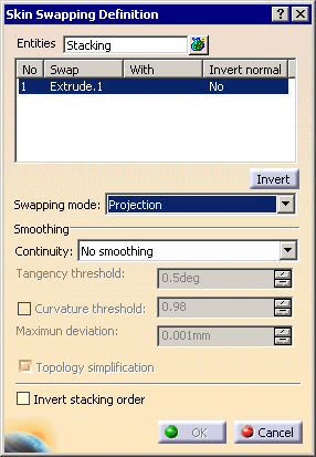
In our scenario, we selected the Stacking (Manufacturing).
The engineering surface to be swapped is already selected in the Swap frame (Extrude.1).

As Edge Of Part and Swapping are not symmetric operations, the skin swapping of an EOP created from plies will not be strictly equal to the EOP created from swapped plies. - Multi-selection of entities
-
Now select the manufacturing surface to be swapped with Extrude.1:
Select Offset.1 in Body.1.
Its name is displayed in the dialog box in the With column.

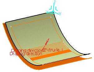
The draping direction is displayed in the 3D geometry.
You can click Invert to reverse the draping direction and be consistent with the direction defined in the engineering plies.
-
Select the Swapping mode (we have kept Projection).

If the data before swapping skins are:
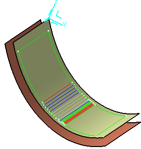
- Projection: The command performs a projection
perpendicular to the destination surface.
The projection of the engineering geometry of the ply from the engineering surface to the manufacturing
surface is only performed on the nearest portion of the manufacturing shell.
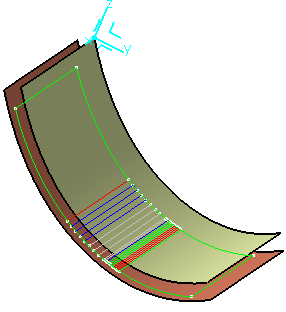
- Elevation: The command performs a projection
perpendicular to the origin surface.

- Unfold: This option provides a complete flatten view
of the Composite plies that will be then
put in actual shape during manufacturing.
The resulting contour is the exact same result as a geometry transfer between the folded and the unfolded surface.
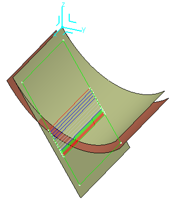
The surface supporting the selected plies must be an unfolded surface of the destination surface,
or the destination surface must be an unfolded surface of that supporting the plies.
If this is not the case, selection is not possible and an error message is displayed.
The unfolded surface must have been created with Surface type set to All - Wrap Curve: See Swapping the Skin with Wrap Curve.
- Projection: The command performs a projection
perpendicular to the destination surface.
-
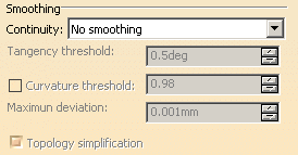
Set the Smoothing parameters:
-
If you have selected a stacking, a plies group or a sequence, the Invert stacking order check box is available.
Select this check box to invert the order of plies during the swapping (we have not selected this check box:- If you have selected a stacking:
- The order of plies groups is inverted (the first becomes the last, the second becomes first before last, etc.),
- Then, in each plies group, the order of sequences is inverted in the same way,
- Then in each sequence, the order of the plies is inverted in the same way.
- If you have selected a plies group:
- The order of sequences is inverted (the first becomes the last, the second becomes first before last, etc.),
- Then in each sequence, the order of the plies is inverted in the same way.
- If you have selected a sequence:
- The order of plies is inverted (the first becomes the last, the second becomes first before last, etc.).
- If you have selected a stacking:
-
Click OK in the Skin swapping dialog box.
The engineering geometry is transferred onto the manufacturing surface.
It is put in the No show space on the engineering surface.
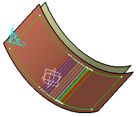
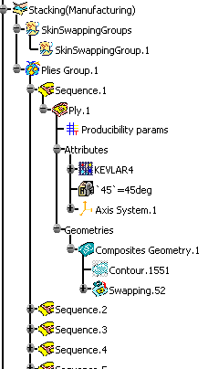
In the specification tree, the Swapping feature (identified as Swapping.xxx) is displayed under each ply.
-
Double-click Swapping.1 element in the specification tree.
-
The Skin Swapping Definition dialog box is displayed.
-
Select the new manufacturing surface.
-
Click OK to perform the modification.
-
Only the ply referencing the feature is modified.
-
Double-click the Plies Group.1 feature in the specification tree.
-
The Plies group definition dialog box is displayed.
-
Click Change. Click No in the message box to edit the existing swapping.
The Skin swapping dialog box is displayed. -
Select the new manufacturing surface.
-
Click OK to perform the modification.
![]()
