that have the same or different numbers of contours.
Open the MaterialExcess1.CATPart document.
EEOP and MEOP with the Same Number of Contours
-
Click Material Excess
 in the Manufacturing toolbar.
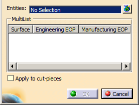
The Material Excess dialog box opens.
-
Select the features where to define the material excess
It can be a ply, a sequence, a plies group, cut-pieces, or a stacking.
In our scenario, we selected the stacking.- Either select one entitiy in the graphic area or the specification tree.
- Or click
 to access the multi-selection dialog box.
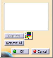
Click to access the
Stacking Management in
selection mode.
to access the
Stacking Management in
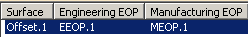
selection mode. - The name or the number of selected entities is displayed in the main dialog box.
-
In the Engineering EOP frame, select the EEOP.1 in the specification tree.
-
In the Manufacturing EOP frame, select the MEOP.1 in the specification tree.
-
Optional: Select the Apply to cut-pieces check box.
The material excess is created for the cut-pieces found in the selected plies, if they exist.
Otherwise, the material excess is computed on the plies themselves. -
Click OK to define the material excess.
Plies are exceeded from the EEOP to the MEOP.
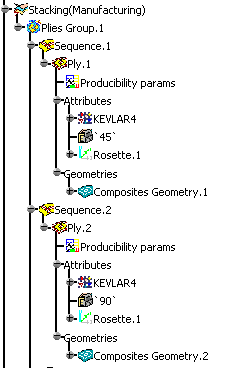
In the specification tree, the element (identified as Material excess.xxx) is displayed under each ply.
-
Double-click the Material Excess feature in the specification tree.
The Material Excess dialog box is displayed. -
Select other elements as EEOP or MEOP.
-
Click OK to perform the modification.
the Gap Offset dialog box appears when you edit the material excess.
EEOP and MEOP with a Different Number of Contours
In this model, the EEOP contains an outer and an inner contour, when the MEOP contains only the outer contour.
 |
 |
| Engineering definition of ply.1 | Manufacturing definition of ply.1 |
-
Click Material Excess
in the Manufacturing toolbar and select the features to
porcess as explained above. -
In the Engineering EOP frame, select the EEOP.1 in the specification tree.
-
In the Manufacturing EOP frame, select the MEOP.1 in the specification tree.
-
Click OK to define the material excess.
Plies are exceeded from the EEOP to the MEOP.
In the specification tree, the element (identified as Material excess.xxx) is displayed
under each ply and contains only one contour.
- This scenario corresponds to the process in
which the cut-outs (inner contours) are removed from
the manufacturing definition of the plies. The manufacturing plies will be nested,
cut and put on the mold without the cut-outs. - In some cases, the MEOP can contain more
contours than the EEOP,
for instance when tooling tabs are added to the manufacturing geometry of the plies.
![]()