You can:
- Create a Shell Constant Offset
- Create a Shell Constant Offset for each Cut-Piece
- Create a Shell Constant Offset for Individual Plies Groups
- Create a Tessellated Constant Offset
- Create a Draped Tessellated Surface
- Create a Draped Tessellated Skin
Be aware that the output surfaces are always datum:
they are not
updated automatically if you modify the input plies.
By-pass: delete them from their contextual menu in the specifications
tree,
and restart Ply Exploder on the modified plies groups.
See Using Non Crimp Fabrics for specific information.
-
Click Ply Exploder
 in the Analysis toolbar.
The Ply Exploder dialog box is displayed.
Create a Shell Constant Offset
therefore no exploded view can be generated.
-
Enter a Scale factor by which each ply thickness is multiplied.
In our example we chose a value of 15mm. -
Click OK to generate the offset surfaces.
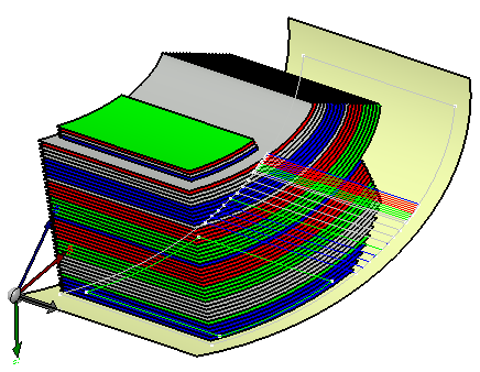
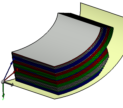
The result is an exploded view of each ply contained in the stacking.
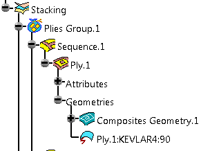
The exploded element is added under each ply in the specification tree.
Create a Shell Constant Offset for each Cut-Piece
In case some plies contains cut-pieces, it is possible to create an offset corresponding to the each cut-piece.
Open the PlyExploder2.CATPart document.
Click Ply Exploder
.Select Take cut-pieces into account in the Ply Exploder dialog box.
Use the default values displayed in the dialog box.
Click OK to validate.
The offset surfaces of the cut-pieces are created.
Create a Shell Constant Offset for Individual Plies Groups
-
Open again the PlyExploder1.CATPart document.
-
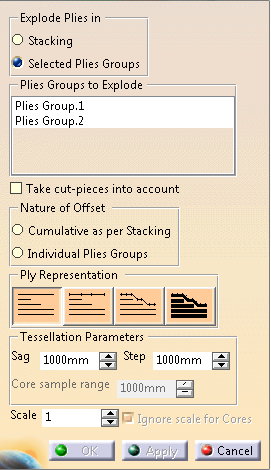
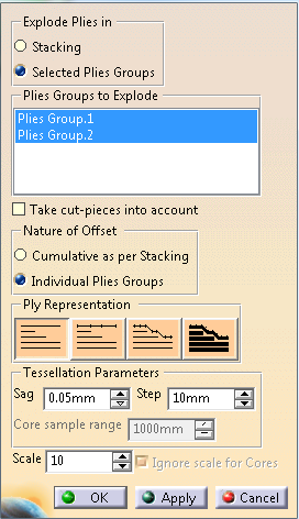
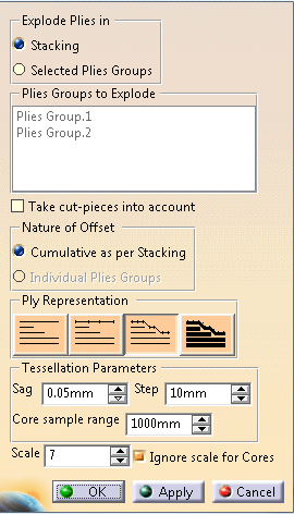
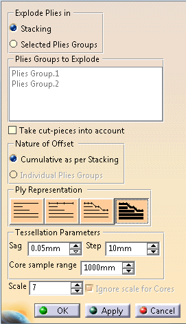
In the Ply Exploder dialog box, select the values as shown below to generate
an exploded view of plies groups 1 and 2.
-
Select the nature of the offset:
-
Cumulative as per Stacking so that all plies
are offset sequentially through the stacking
or -
Individual Plies Groups so that all the plies
belonging to a plies group are offset sequentially
through the group. The offset value is set back to zero each time the system switches to another plies group.
In our example we selected Individual Plies Groups.
-
Cumulative as per Stacking so that all plies
are offset sequentially through the stacking
-
Enter 10 as scale factor.
-
Click OK to generate the offset surfaces.
-
Right-click Plies Group.1.
-
Select Plies Group.1 object, then Hide/Show 3D contour.
-
Right-click Plies Group.2.
-
Select Plies Group.2 object, then Hide/Show 3D contour.
Now, only the exploded plies are displayed.
-
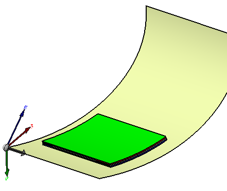
Select Plies Group.1 object again, then Hide/Show Exploded Surface.
The exploded surface of Plies Group.2 only is displayed.
Create a Tessellated Constant Offset
to a constant offset of the ply shell, as when using the Shell constant offset representation.
-
Open again the PlyExploder1.CATPart document.
-
Click Ply Exploder
in the Analysis toolbar. -
In the Ply Exploder dialog box, select Tessellated Constant Offset
and set the values as shown below.
- The Sag and
Step parameters enable you to
refine the tessellation:
- The sag parameter defines the maximum distance
between the geometry
and the triangles making up the tessellated surface, - The step parameter defines the maximum size of the triangles making up the tessellated surface.
- The sag parameter defines the maximum distance
between the geometry
- The Core Sample Range parameter defines the depth of
the sampling for each point of tessellation
perpendicular to the shell.
-
Click OK to generate the exploded view.
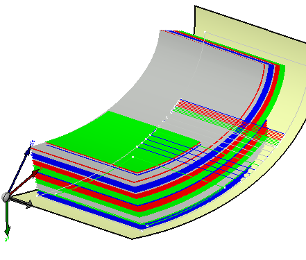
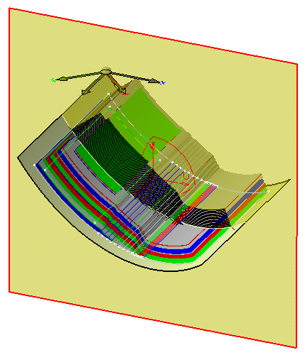
Create a Draped Tessellated Surface
corresponding to a variable offset of the ply shell.
An offset of each point of the mesh is generated according to the real value of the core sample,
multiplied by the scale factor.
This view provides a realistic 3D view of the stacking and allows you to create realistic section views in drawings.
-
Open again the PlyExploder1.CATPart document.
-
Click Ply Exploder
in the Analysis toolbar. -
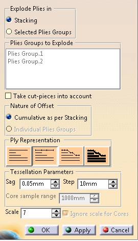
In the Ply Exploder dialog box, select Draped Constant Offset and set the values as shown below.
-
Optional: Select the Ignore scale for Cores check box.
This option is availabe and selectable for Draped Tessellated Surface only.
(Scale for cores is ignored by other modes)
The scale factor is not applied to the core when exploding the plies.
The core thickness remains unchanged, only that of the plies is scaled. -
Click OK to generate the exploded view.
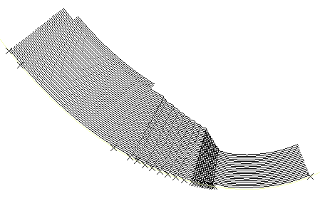
Closer view
You are now going to create a section view of the part. -
To do so, go to the DMU navigator workbench, via Start>Digital Mockup>DMU Navigator.
-
Copy-paste the Composites part in the DMU Navigator workbench.
-
Click Sectioning
 .
.
A section plane is defined on the part and a section view is generated.
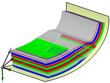
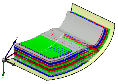
Create a Draped Tessellated Skin
You can create a draped tessellated skin.
This type of exploded view
generates a closed skin that represents all the exploded plies.
For all
plies, a draped tessellated surface is generated as described above,
then an
offset equal to the scale x ply thickness is applied and triangles are added
to create a closed skin.
-
Open again the PlyExploder1.CATPart document.
-
Click Ply Exploder
in the Analysis toolbar. -
Select Draped Tessellated Skin and set the other values.
-
Click to generate the exploded view.
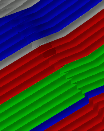
Closer view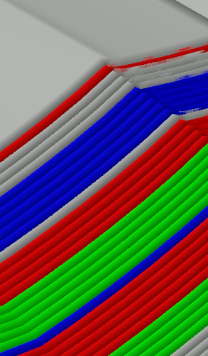
![]()