As in Defining the Panel:
- Ramp preview is available as Virtual Stacking Drops.
- Double-click a staggering to edit is.
Virtual Stacking supports the master stacking sequence mode.
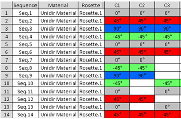
If all the laminates used on grid cells are defined from the master stacking sequence, the stacking sequences are aligned as shown below.
This master stacking sequence with cell C1 pointing to Laminate.1, C2 to Laminate.2, C3 to Laminate.3
| Material | Laminate.1 | Laminate.2 | Laminate.3 |
| Unidir Material | 0 | 0 | 0 |
| Unidir Material | 45 | 45 | 45 |
| Unidir Material | 90 | 90 | 90 |
| Unidir Material | -45 | -45 | -45 |
| Unidir Material | 0 | 0 | 0 |
| Unidir Material | 45 | 45 | 45 |
| Unidir Material | 0 | 0 | |
| Unidir Material | -45 | -45 | |
| Unidir Material | 90 | 90 | |
| Unidir Material | -45 | -45 | |
| Unidir Material | 0 | 0 | |
| Unidir Material | 45 | 45 | 0 |
| Unidir Material | 0 | 45 | |
| Unidir Material | 45 | 45 |
-
Click
 Virtual Stacking in the Grid Design
toolbar and select a
Grid:
Virtual Stacking in the Grid Design
toolbar and select a
Grid:- A Grid Virtual Stacking node is created in the specification tree,
- The Virtual stacking management dialog box
opens.
It consists of a 2D viewer, also referred to as the table, and several options.

- The Tools Palette opens.

It offers several commands to help you manage the virtual stacking: -
Select

-
Repeat

-
Recomputation
from Grid

-
Maximize Symmetry

-
Merge
domains

-
Create a
new Stacking
Area

-
Check
Ply Rules

-
Single
Row edition

-
Multiple
Row edition

-
Cell
valuation
-
Apply Master
Stacking
Sequence
Laminate

-
Move Row

-
Swap
Rows

-
Duplicate
Row

-
Insert
Blank Row
(sequence or
ply)

-
Cut Row

-
Copy Row

-
Paste
Row

-
Select
Row from
Cell

-
Display the table according to your needs:
- Resize the dialog box to enlarge the 2D viewer.
- Zoom in or out, or pan the table as you need, using standard V5 commands.
- This 2D viewer displays Composites cells with background colors that correspond to the ply orientation colors.
- If you have selected this options in Tools > Options, place the cursor over a cell in the 2D viewer to display information about that cell, e.g. the sequence or the ply the cell belongs to, its material, its orientation, its name.
Combine the Entity level (Sequence or Ply) and the View mode (Cells or Stacking areas) to retrieve and display the information you need.
-
Press Compare with Current State
 .
.
- The current cell coverage of all elements is stored.
- All Tools Palette commands that have an impact on virtual element cell coverage remain available,
- All Tools Palette commands that have an impact on virtual element order are disabled.
- When you launch a
Tools Palette
command, the new
coverage is compared
with the stored one,
and information on differences is displayed via visual effects:- In
the 2D
viewer:
- Added cells are displayed with a white border,
- Removed cells are displayed with a black border.
- In
the
authoring
window:
- Differences are visualized when you select a virtual element.
- Additions are symbolized by a darker orientation color,
- Removals are symbolized by a darker gray color.
- In
the 2D
viewer:
- When you release
,
the stored information
is lost.
All virtual elements found with an empty cell coverage are removed.
An information message is displayed.
-
Make a review:
-
Go to the Symmetry Management:
-
Press one of the icons under Preview to visualize the shape of the plies without generating them.
The icons correspond to the algorithms used by Plies From Virtual Stacking.
- Minimum Crossing
- Minimum Crossing & Weight Saving
- Weight Saving
- Drop Off Order. Available if Layer Levels are defined in the Master Stacking Sequence.
The visualization is computed using the latest values used in Plies From Virtual Stacking.
They are proposed until you press one, or until a re-computation is needed.
Note that:- Multi-selection of plies is supported.
- Preview lines may be distant from the actual plies.
- Once computed, these previews are displayed instead of the plies.
- Small gaps or overlaps of preview lines may occur.
- Preview of steps resulting from a ramp support with no clearance are not centered.
-
Select Display 3D Information to display information in the authoring window:
-
Click Display Info Table to display an additional information table.
In this table, if the current thickness law is different from the stress thickness law, the cell will be colored:
- In red if the current number of plies is lower than the stress.
- In yellow if the current number of plies is greater than the stress.
- Stacking areas are computed
from the cells that share the same
stacking sequence
and are dynamically updated.
-
Click More...
Additional options appear. -
- Click ... to define the path of the export file.
- A message informs you whether the export has been successful or not.
- If the number of columns required is greater than 256, the export result is written over several worksheets.
- In Stacking areas View mode, the list of the cells corresponding to each stacking area is added to the .xls file.
- Export to .xls file does not export the background colors of the cells.
-
Click ... to define the path of the import file.
The display mode is updated according to the .xls file imported.
If you have changed the names or materials of plies or sequences,
this is detected and processed by the Synchronize stacking command.
If the import leads to a virtual stacking incompatible with the master stacking sequence, the import fails.
A message informs you whether the import has been successful or not. -
Select Highlight Real Sequence or Ply
When you select a line in the dialog box, the corresponding real sequence or ply is highlighted in the authoring window, when it exists.
By default, this check box is selected. -
Select Force Automatic Merge on Sequence or Ply when needed.
By default, this check box is selected. -
Use the Undo/Redo arrows as necessary on virtual stacking commands.
![]()