 |
This task shows you how to define Grid Panels in several steps, each
step having its own dialog box:
|
|
|
- This task is available in the CATIA Composites Engineering (CEG)
product.
- This task is available in the Composites Grid Design workbench.
|
 |
- The last two options are not proposed if the reference element has
not been created from a surface.
- You can edit the parameters of a Reference element group or a
Reference element via a formula.
- When you edit a Reference element group, you apply the values of those
parameters as formulas to all the reference elements of the group.
- Sub-staggering data will be taken into account when you will
generate the plies.
- Centered ply drop under Clearance
has been renamed Centered Ramp Support.
|
 |
Open PanelStart01.CATPart
from the samples directory. |
 |
-
Click
Grid Panel
 in the Grid Design toolbar.
The Panel definition dialog box is displayed.
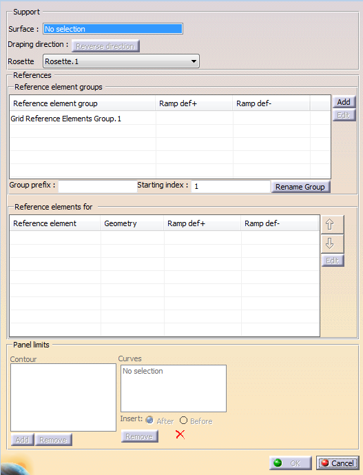
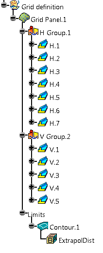
A Grid definition node is created in the specification tree.
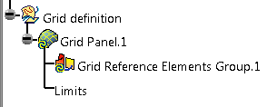
A
Grid Reference Elements Group is proposed in the dialog box and
created in the specification tree.
For the moment it is empty.
Its default name is
Grid Reference Elements Group.x.
You can edit this name: Key in the required name in
Group prefix and click
Rename Group.
-
Select MOLD as the
Support Surface.
Note that holes are not allowed on the support surface.
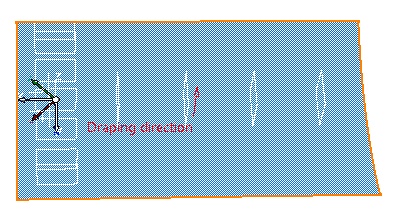
The
Draping direction is displayed in the 3D viewer.
If necessary, click Reverse direction in the dialog box,
or click the red arrow in the 3D viewer to invert the Draping
direction.
-
Select the Rosette from the list.
See
About Rosette and Rosette Transfer Type for
more information.
-
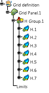
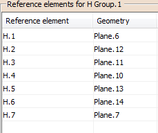
Create one
Reference element
group with the
Group prefix H:
- Select the grid Reference Elements Group.1 in the dialog box
- Optional: Enter H as the Group prefix,
and click Rename Group.
The name is updated.
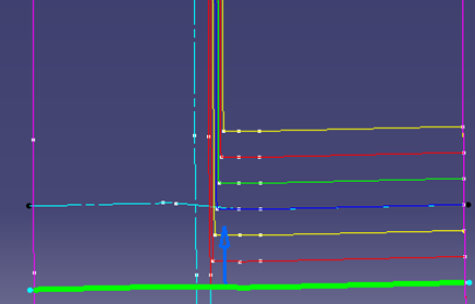
- Select the elements in the 3D viewer.
Reference elements
(e.g. ribs and stingers) can be either:
- Curves
- Or surfaces or planes.
- The ramp support is previewed in the
graphic area.
- A warning is displayed if several Reference elements have the
same name.
- If a reference element is closed, it is split into 3
sub-elements with the same staggering information
as the original reference element.
- A contextual menu is available to remove or replace a
Reference element, as well as arrows to reorder them.
- If a Grid has been created, new cells can appear or others
can be removed.
In that case, the Stacking Areas Table, Sequence
Shape even the Plies contours will be updated.
- If you edit an existing Grid Panel and you need
to edit a Reference element group, select it in the dialog
box
to display the list of its elements.
|
-
They are added to the specification tree and to the
dialog box:
-
A grid panel may contain several Reference element
groups.
Click Add in the Reference element groups frame.
A new Reference element group is added both in the dialog box and in the specification tree.
Enter V as the Group prefix and select the
vertical planes.
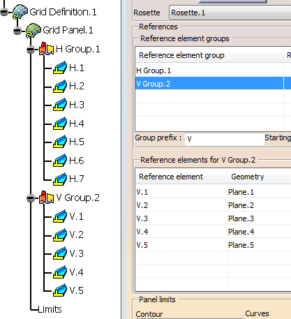
A contextual menu is available to remove Reference element groups.
|
| |
-
Optional: Define the
limits of the panel (i.e. the Edge of
Part). They will show the
part boundaries and its holes.
Although Panel limits are known and can be defined early in
the design while defining the Panel,
designers often prefer
to work without limiting the plies before having reached the stage
where
the design is almost finished and detailed.
For this reason, the limit
contour defined as Panel limits will actually limit the plies
once you have activated it
with the Limit plies from panel limits
command.
See
Limit plies from panel limits.
-
Click Add in the Panel limits frame.
A contour is added in the dialog box.
-
Select curves so that they form a closed contour.
A green tip replaces the red cross.
-
Use Insert After, Before
and Remove to modify the order of the curves as well as
the contour.
-
Use the contextual menu to create the curves of the contour
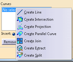
|
|
|
|
If you define the Limits of the Grid Panel, the ExtrapolDist parameter that has been defined
in the
Zone Definition dialog box is
stored under the contour of the Grid Panel.
It is visible in the dialog box when you re-open it:
- If you are editing an existing Grid Panel, this parameter is
editable too.
- If you are editing an existing Grid Panel, and change
the Side attribute of a limit contour,
a warning message will be
displayed as this will impact the ply.
- An arrow lets you decide of the limitation side of limit contours.
- You can define several Grid Panels in the same CATPart.
|
| |
-
Click OK to validate and exit the dialog box.
The Grid Panel is created in the specification tree:
and in the 3D viewer:
|
|
|
Editing a Reference Elements Group
You can edit a reference elements group to select a default ramp
definition.
This ramp definition is applied to elements already in the
group, as well as to the elements you add in the future.
For more information, see Specifying a Ramp
Definition.
-
To edit a reference elements group, either:
- Select it in the Panel definition dialog box and
click Edit.
- Or, once it has been created, double-click it in the
specification tree.
- Or, once it has been created, right-click it in the
specification tree and select Definition.
|
Continue as explained below for a reference element with the difference that there is no sub-staggering. At validation, if reference elements already existed in the group, select how to propagate the changes. The defined values are stored as parameters under each element of the reference elements group. |
|
|
You can edit a specific staggering for a Reference element:
Reference
elements can be divided into sub-elements, with
specific staggering information that overrides the global information.
For a quick definition of the slope, contextual menus on elements in the
graphic area provide direct change of the parameter values,
using values
defined elsewhere in the Reference Element or the Grid Panel.
Modification applies on both sides, if applicable, or on selected side
otherwise.
See also About Staggering Edition
-
To edit a Reference element
either:
- Select it in the Panel definition dialog box,
and click
Edit
- Or, once it has been created, double-click it in the
specification tree
- Or, once it has been created, right-click it in the
specification tree
and select Definition in the contextual menu.
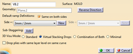
Geometry information (Surface and Geometry) is displayed but
not editable.
|
-
Click Reverse Direction or the arrow in the
work area to invert that staggering direction.
-
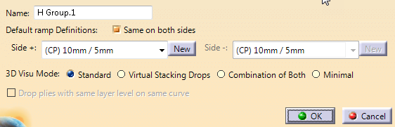
Specify default ramp definitions.
- Decide to have the same ramp definition on both
sides or not.
- From the list of Side +, select the
ramp definition to apply as default.
Depending on the
geometry, not all ramp definitions are proposed:-
Offset/Offset ramp definitions are not
proposed if the input geometry is not a surface of a
plane.
- Between two curves, Angle
to curve and Custom ramp definitions
are not proposed if the input curves are not on the
same reference surface as the Grid Panel Surface.
- Alternatively, click New and specify a new ramp
definition.
- Repeat on Side - if you have cleared Same on both
sides option.
- Select the blank item in the list if you do not want
to apply a ramp definition to the reference element.
|
-
Add a Sub-Staggering.
The default ramp
definition is proposed.
-
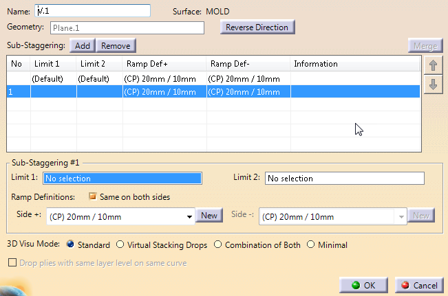
Check and manage the sub-staggerings.
- Select one sub-staggering in the table.
It is
highlighted in the work area.
- Check the information in the work area or in the table
(Overlapping or adjacent sectors).
- Select two adjacent sub-staggering sectors (sharing a
common reference element) and click Merge.
- Right-click an information tag to edit the staggering
or replace it with one of the availabe ramp definitions.
|
-
Use the arrows to re-order selected sub-staggerings.
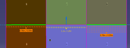
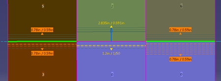
-
Select a sub-staggering and the two elements (Limit 1
and Limit 2) that relimit the sub-element.
- As you select the relimiting elements, they are
highlighted in the work area.
- The sub-element is displayed in green in the work
area.
|
-
Alternatively, in the graphic area, place the pointer
over a valid reference element.
Click the scissors that appear.
Relimiting elements are automatically set, the sub-staggering is
created.
-
Select a geometry to define the direction for Side +.
A contextual menu is available.
-
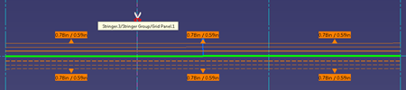
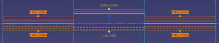
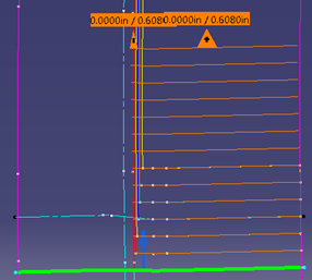
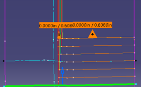
Define how ramps are visualized in the work area.
- An arrow shows the orientation of the reference
elements.
- Clearance and slope values are displayed. They are
editable by their contextual menu.
- Side+ is identified by solid lines, Side- by dashed
lines. These lines do not lie on the reference surface,
but on a 3D plane tangent to the surface. As a
consequence, they are sometimes distant from the
corresponding ramp support curves.
- Sub-staggering sectors are identified in different
colors.
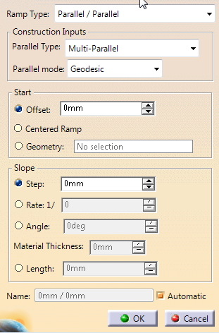
- When the slope is defined by a ratio, the step is
computed from the thickest material of the plies.
- Active staggering (the one selected from the list) is
highlighted.
- The preview is automatically updated.
- Standard: Each ramp is visualized by 3
curves on each side.
This is the only possible mode
when no or more than one Virtual Stacking exists.
- Virtual Stacking Drops: The number of
displayed curves varies with the number of plies dropped
in Virtual Stacking.
- Combination of Both: Same as Virtual
Stacking Drops, with a minimum of 3 curves displayed on
each side.
The curves are displayed in low intensity
if no ply drop applies.
- Minimal
|
|
 |
For more information,
see About Staggering Edition.
-
When Virtual Stacking Drops is selected,
select Drop plies with same layer level on same curve.
The reference element visualization considers that plies with the same
layer level are on the same curve.
For example, plies generated as
follows
are visualized like this when the option is cleared.
and like this when the option is selected
We recommend you select this option when plies are generated with the
option Drop plies same layer level on same curve.
The Sub-staggering information are taken into account
while generating the ramp supports.
|
|
 |