Edit One Single Row
- Lock symmetry is not taken into account for Cell dispatch, that works for non-symmetric layers or for the upper symmetric layers only.
- All attributes can be modified.
- Orientation, material and cell coverage are transferred to lower symmetric layers.
- When the Entity level is set to Ply, Material, Direction and Rosette are not available if you have selected and intend to modify only some of the plies belonging to a sequence: modifying those properties for only some plies of a sequence that contains more would lead to a sequence with several rosettes, orientations or material.
-
Set Entity level to Ply and View mode to Cells.
-
Select the row of Ply.5 in the 2D viewer.

The corresponding cells are highlighted in the 3D viewer.
In the 3D viewer, the cells of the selected ply are displayed in the color of their direction,
the information in the dialog box is displayed on a background of the same color.
-
Click Single row edition (geometry and properties)
 in the Tools Palette.
Single row edition (geometry and properties) is also available from the row contextual menu.
The Single row edition (geometry and properties) dialog box is displayed:
Note that Sequence name is not available when Entity level is set to Ply. -
Pick cells C20, C21, C6, C4, C11 and C8 in the 3D Viewer and click Cell dispatch in the dialog box:
- In the 3D viewer, those cells are displayed with a sign
indicating
that they could be either removed from or added to Ply.5.
-
 indicates the cells that can be removed from the ply
you are editing,
indicates the cells that can be removed from the ply
you are editing, -
 indicates the cells that can be added to the ply you
are editing.
indicates the cells that can be added to the ply you
are editing.
-
- In the dialog box,

- Sources displays the plies the cells you have picked belong to,
- Recipients displays the plies you could send those cells to.
In the following two steps, you will check the plies in the Recipients and in the Sources lists:
- In the 3D viewer, those cells are displayed with a sign
indicating
-
Select Ply.8 in the Recipients list.
According to the status of the cells:
-
 indicates that the cells can not be moved.
 -
 indicates cells that can be removed from a ply,
 -
 indicates cells that can be added to a ply,
 -
 indicates that you have validated the proposal,
either addition or removal,
indicates that you have validated the proposal,
either addition or removal,
The display in the 3D Viewer changes to:
indicates the cells that could be added to Ply.8.
Pick the on C6 and C4.
is replaced by a green validation mark
and the name of the ply the cells belong now to.
-
-
Select Ply.14 in the Recipients list. The display in the 3D Viewer changes to:
identifies cells that cannot be added to the ply.
Continue to check all plies in the Recipients list.
For Ply.49, validate C20 and C21:
-
Now check the plies in the Sources list. For Ply.54 validate the removal of C11.
-
Click OK to validate and exit the Edit row dialog box. Select the row of Ply.5 again.
It now looks like this:
Note that the modification of the orientation of a ply or a sequence is taken into account by the symmetry.
Edit Multiple Rows
-
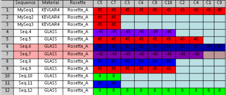
Lets consider a virtual stacking that looks like that:

- In the first column (Sequence) the names start with Seq.
- In the second column, the Material is Glass for all rows.
- The Direction of the first and third rows is 0, shown in green,
- The Direction of the second row is 90, shown in dark blue,
-
Click Multiple Row Edition
 in the Tools Palette and select several rows, e.g. the first three rows.
Multiple Row Edition is also available from the row contextual menu.
Multiple Row Edition does not work with Lock Symmetry.
The Multiple row edition dialog box opens. -
In that dialog box
![]()