For a problem-free generation of plies, we recommend that:
- The cells are defined by a closed contour made of at least 2 reference elements,
- The cells should not use more than two nodes per reference
elements
(e.g. L-shape cells are OK, U-shape cells are not).
See About Plies Creation from Virtual Stacking for more details.
Open ManageDropOff01.CATPart from the samples directory.
-
Click Plies From Virtual Stacking
 in the Grid Design toolbar.
Note that the content varies with the selected algorithm.
or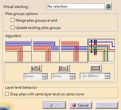
-
Select one or several virtual stackings, for example Grid Virtual Stacking.3 in the specifications tree.
Tip: Select a grid container to select all the virtual stackings it contains.
-
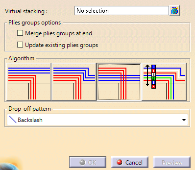
Select the algorithm you want to use:
-
 Weight saving
manages the drop-off pattern locally:
Weight saving
manages the drop-off pattern locally:

The closest ramp support curves are used for the plies corresponding to the longest ramp entity.
The drop-off pattern is managed ramp entity by ramp entity.
-
 Minimum Crossing
manages the drop-off pattern globally:
Minimum Crossing
manages the drop-off pattern globally:

-
 Minimum crossing & Weight Saving
manages the drop-off pattern from three criteria,
Minimum crossing & Weight Saving
manages the drop-off pattern from three criteria,
respectively length, height and surface (L*H).
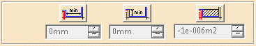
Click the corresponding icon to activate the criterion and enter the required value.
If one measure is below the criterion, the staggering is not created. -
 Drop-off order based on layer level
uses the layer level of each virtual sequence as a drop-off
order value to stagger plies.
Drop-off order based on layer level
uses the layer level of each virtual sequence as a drop-off
order value to stagger plies.
Make sure the layer levels are unique.
Available when layer levels are defined on each virtual sequence.
See About Master Stacking Sequence for more information.
Drop-off pattern is not available with this option.
-
-
- If Merge plies groups at end is not selected, plies groups are updated if requested, provided they have been generated with the selected algorithm.
- If Merge plies groups at end is selected,
Update existing plies group is always activated.
- If a plies group corresponding exactly to the current selection of virtual stackings is found, the plies group is updated.
- If none is found, a new plies group is generated.
-
Where relevant, a default drop-off pattern is proposed.
If necessary, select another one from the list:
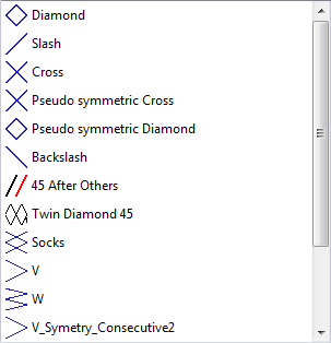
The drop-off pattern takes the orientation of plies into account.
Note that pattern can be defined in all propagation mode, except in MSS as drop-off orders are defined by desin in MSS. -
For Drop-off order based on layer level, if required, select Drop plies with same layer level on same curve.
-
Click Preview. The ramp supports and the plies are computed:
- Ramp supports are grouped by structural elements groups and by
side:
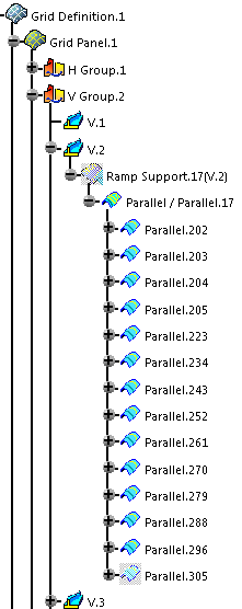
- The stacking is generated with ply contours based on
the ramp entity curves.
- In order to reduce the number of useless ramp support
curves,
one ramp support is created for each structural element per side (+1 and/or-1).
- Ramp supports are grouped by structural elements groups and by
side:
-
Click OK to validate and exit the dialog box.
![]()