|
|
Before V5R18
- Zones are linked, via the laminate, to materials inside a CATMaterial.
If the CATMaterial is not available, the zone laminate is KO and the
following cannot be created:
- Plies from zones,
- Solid/top surface from zones.
- Each ply is linked to a material inside the CATMaterial
if the CATMaterial is not available, the ply is KO and the following
cannot be created:
- Solid from plies
- Exploded surfaces
- Producibility/ Flatten
- etc.
In short, nothing can be done with a Composites CATPart if the
corresponding CATMaterial is not available, which causes numerous issues
especially when sending models to a partner for example.
In V5R18 and Above
Starting with V5R18, you can define the Composites Parameters by
selecting only the required materials from one or several catalogs,
instead of selecting a whole material catalog. This enables the
Composites Parameters to store a list of material cache features
that will each have:
- a list of knowledgeware parameters corresponding to the material
properties needed to update the CATPart even if the material catalog is
not available,
- a link to the corresponding material in a material catalog.
Please note:
- Pre-V5R18 models need to be updated.
- You can define a material as
NCF.
- Not all material parameters are stored in the Composites Parameters.
This means that a FEA analysis cannot be
performed if the catalog is not available.
- The materials proposed in the commands defining zones and plies are
only those defined in the Composites Parameters.
- Instead of having an applied material like in previous releases, the
ply will only a point to the corresponding material cache available in
the composites parameters.
You can no longer apply a material at a ply level.
Replacing a material in all plies will be done through the
rerouting of the material link.
- The laminate feature of zones will no longer point to the materials
in the CATMaterial like in previous releases.
It will now directly point to the Composites materials stored under the
Composites Parameters. This will be transparent for the user.
About Material in Composites Braiding
Most material catalogues have
a fabric width that matches the width of the material when used in a hand
lay-up. When working in Composites Braiding, we recommend that you create
a material catalogue with the same materials, but with thicknesses and
widths that match the tows used by the braiding machine. As the dialog
box is populated with this data when you select a material, it is useful
to have a material catalogue that contains sensible default values. The
dialog box will list materials with their name and width x thickness
About Laminates
The main input for the Composites designers are:
- The reference surface that supports the plies
(master geometry),
- The zone map and stacking table coming from the
stress office, resulting from a FEA analysis.
The stacking table (typically given as a spreadsheet)
defines the requested laminate for each zone of the
reference surface. The laminates ensure that the structure
will resist to the expected stress.
A laminate can be given as:
- A stacking sequence, that defines precisely the
stacking as an up-down ordered list of layers,
characterized by their material and orientation,
- Or as a thickness law, that only indicates the
number of layers for each couple of material/direction
used.
A thickness law can easily be retrieved from a stacking
sequence, whereas several stacking sequences correspond to a
same thickness law.
The laminate is dealt with differently by the Grid Approach and the
Solid Approach:
- In the Solid Approach, the laminate is explicitly
implemented as a feature visible in the specification
tree, under each zone. The laminate is defined for a
given zone, and can only be edited as a thickness law:
for one or several materials, the number of layers is
given for each possible orientation. Designers can
select an existing laminate in the specification tree
and fill in the thickness law directly from it.
- In the Grid Approach, the laminate is not explicitly
implemented as a feature, and is not visible in the
specification tree. For each cell of the grid, the laminate
can be defined as a stacking sequence, or as a thickness
law. Two laminates can be defined: the reference one, and a
modified one. Laminates can be defined globally for all the
cells by importing/exporting a grid definition file, and
stacking can be propagated to several cells.
In V5-6R2013 and Above
Laminates have been enhanced to extended laminates:
- Extended laminates can be defined at the start of
the design, using the Composites Parameters command, or
later, while editing grids or zones.
- The extended laminates can be
explicitly defined either as a stacking
sequence or a thickness law, using the
Composites Parameters command, in both
Grid Approach and Solid Approach.
Definition as a stacking sequence is
possible in Solid Approach, for
compliance reasons. However, the
laminate is considered as defined by a
thickness law, meaning the material is
defined for a given zone and edited only
as a thickness law.
- They can also be implicitly defined when
importing grid data from external data or
from a virtual stacking: extended laminates
are created if existing ones do not cover
the needs, i.e. if the stacking used for a
cell does not correspond to an existing
extended laminate.
- Both Excel and text file formats are
supported to define the laminates
through import/export capabilities.
- New laminates can be created on the fly,
without exiting the grid cell or zone
definition commands. They will be visible
under Composites Parameters.
- Automatic
creation of extended laminates with grid
cell or zone definition commands can be
de-activated, to ensure that only validated
extended laminates are used (e.g. to ensure
compliancy with in-house rules).
- Information is displayed when
extended laminates have been created
after an import, or when automatic
creation is disabled and missing
laminates are found.
- The list of laminates is visible at a glance under the
Composites Parameters node in the specification tree.
- Existing laminates are easy to re-use.
- Laminates can be renamed to meet a company
standards.
- A color is associated to each laminate for a more
stable 3D visualization.
- Each cell of a grid (Grid Approach), or zone (Solid
Approach) points to an extended laminate to define its
local stacking. A grid cell can point to two extended
laminates (reference and modified).
An automatic migration to extended laminates is started
when you open an old model, that creates a laminate object
for each stacking/laminate found in grids and zones.
About Master
Stacking Sequence
You can import a spreadsheet defining a Master Stacking Sequence and
all associated laminates to be used in a model (one laminate per column).
It looks like follows:
| Material |
Laminate.1 |
Laminate.2 |
Laminate.3 |
Laminate.4 |
Laminate.5 |
Laminate.6 |
| Unidir Material |
0 |
0 |
0 |
0 |
0 |
0 |
| Unidir Material |
45 |
45 |
45 |
45 |
45 |
45 |
| Unidir Material |
90 |
90 |
90 |
90 |
90 |
90 |
| Unidir Material |
-45 |
-45 |
-45 |
-45 |
-45 |
-45 |
| Unidir Material |
0 |
0 |
0 |
|
|
|
| Unidir Material |
45 |
45 |
45 |
|
|
|
| Unidir Material |
0 |
0 |
|
0 |
|
|
| Unidir Material |
-45 |
-45 |
|
-45 |
|
|
| Unidir Material |
90 |
90 |
|
90 |
|
|
| Unidir Material |
-45 |
|
-45 |
|
|
|
| Unidir Material |
0 |
|
0 |
|
|
|
| Unidir Material |
45 |
45 |
|
|
|
|
| Unidir Material |
0 |
|
0 |
|
|
|
| Unidir Material |
45 |
45 |
45 |
45 |
45 |
|
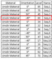
In the model, this import generates or updates:
- A Master Stacking Sequence (first two columns), which is an
ordered list of layers, defined by a material and an orientation (as
shown in the red squares below) and a layer level and a layer name
(optional, can be left blank). Once generated, the Master Stacking
Sequence can be used
to create the virtual stacking.
Example of layer with layer level
and layer name:
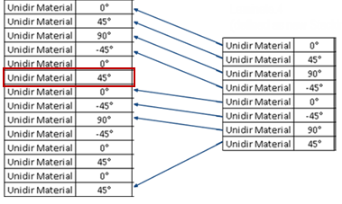
- Stacking sequence laminates (following columns) linked to the
Master Stacking Sequence as shown below, where:
- The Master Stacking Sequence is on the left, the stacking
sequence laminate is on the right.
- The first column lists the materials while the second lists
the directions.
- Optionally, the second line of the spreadsheet can contain a
color index for each laminate. All color indices, if any, must be
unique. In that case, the format of the file changes slightly.
| Material |
Orientation |
Laminate.2 |
Laminate.3 |
Laminate.4 |
Laminate.5 |
Laminate.6 |
|
ColorIds |
16 |
17 |
18 |
19 |
20 |
| Unidir Material |
0 |
0 |
0 |
0 |
0 |
0 |
| Unidir Material |
45 |
45 |
45 |
45 |
45 |
45 |
| Unidir Material |
90 |
90 |
90 |
90 |
90 |
90 |
| Unidir Material |
-45 |
-45 |
-45 |
-45 |
-45 |
-45 |
| Unidir Material |
0 |
0 |
0 |
|
|
|
| Unidir Material |
45 |
45 |
45 |
|
|
|
| Unidir Material |
0 |
0 |
|
0 |
|
|
| Unidir Material |
-45 |
-45 |
|
-45 |
|
|
| Unidir Material |
90 |
90 |
|
90 |
|
|
| Unidir Material |
-45 |
|
-45 |
|
|
|
| Unidir Material |
0 |
|
0 |
|
|
|
| Unidir Material |
45 |
45 |
|
|
|
|
| Unidir Material |
0 |
|
0 |
|
|
|
| Unidir Material |
45 |
45 |
45 |
45 |
45 |
|
- Material ID and orientations must correspond to those
existing in the model.
- All orientations must be the same on a given line and one
orientation must be set for each line.
|
|
|
Master Stacking Sequence and Composites Parameters
- If defined for one line, the layer name must be defined for all,
and be unique.
- If defined for one line, layer level must be defined for all and
be a numerical value.
- Material ID and orientations must correspond to those existing in
the model.
- All orientations must be the same on a given line and one
orientation must be set for each line.
- All color indices, if any, must be unique.
- Laminates in the model are not deleted if not present in the
imported file.
- Imported laminates are displayed in the Laminates tab
and marked SS-MSS.
- Laminates previously defined from a Master Stacking Sequence, that
have become incompatible with the newly imported Master Stacking
Sequence, are turned into standard stacking sequences. A warning is
displayed.
- If a virtual stacking had been created from a Master Stacking
Sequence and has become incompatible with the newly imported master
sequence, a warning is displayed and the link to the Master Stacking
Sequence is lost.
- Existing laminates are updated with the information of imported
laminates with the same name.
- Each laminate receives a color index, the one contained in the import
file if it exists, an automatic one otherwise.
If you re-import a Master Stacking Sequence, the current
Master Stacking Sequence and its associated laminate are updated.
- When an existing laminate corresponds to a re-imported one, it is
updated.
- When an existing laminate does not correspond to any re-imported
one, its compatibility is checked.
If it is compatible, it remains
associated to the Master Stacking Sequence, otherwise, it is changed
into a standard Stacking Sequence.
- A laminate is compatible with a new Master Stacking Sequence if
its layers are an ordered sub-set of all layers of the Master Stacking
Sequence.
- When an existing laminate corresponds to a
re-imported one, it is updated at re-import (change of layer level
or sequence name).
- Swap of laminates, deletion of a laminate, change of a material or
orientation of a layer are not supported.
Master Stacking Sequence and Grid Definition
- When these Stacking Sequences are used in Grid Definition, the
virtual stacking is created from the order of layers in the Master
Stacking Sequence.
When defined, the layer lever and layer name
provide respectively the level data and sequence name of the generated
virtual sequence in the Virtual Stacking.
- Layer information (level and name) is applied to each virtual
sequence of the Virtual Stacking.
- Layer levels are stored on each virtual sequence.
- In the
Ply entity level view, the layer level is identical for each ply of
the same sequence.
- Information display in Virtual Stacking is adapted to the Master
Stacking Sequence information.
- At ply generation, layer levels can be used as drop-off order,
enabling you to drive the staggering from layer levels defined
externally.
Definition via Export/Import
You can define laminates by exporting their definition as an external
file, modifying it and re-importing it.
Both Excel and text files are
supported.
Example of definition:
Name TL.1
ColorIdx 1
Type TL
Stacking 0 45 -45 90
U174_T800 18 6 6 4
#
Name SS.1
ColorIdx 2
Type SS
Stacking
U174_T800 0
U174_T800 45
U174_T800 45
U174_T800 45
U174_T800 -45
U174_T800 -45
U174_T800 -45
U174_T800 90
U174_T800 90
U174_T800 -45
U174_T800 -45
U174_T800 -45
U174_T800 45
U174_T800 45
U174_T800 45
U174_T800
0
#
Name TL.2
ColorIdx 3
Type TL
Stacking 0 45 -45 90
U174_T800 20 6 6 4
#
|