Initialize the Process
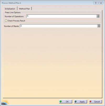
Define the Part
-
Go to the Method Plan tab.
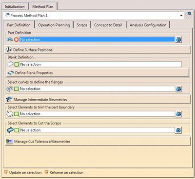
Use the contextual menus under the items to create missing geometries. In the Part Definition tab select a Process Method Plan.
-
If needed, click
 to open the Method Plan dialog box.
 Press Define Surface Positions.
See Defining the Positioning for more information.
-
If required, press Define Blank Properties.
See Defining the Blank Material Properties for more information.
Material and Thickness are stored under the model and not yet used in the concept process. -
Select the elements to cut the surface.
They are the curves that split the result of the positioning to define folded areas. -
Press Manage Intermediate Geometries.
See Creating a Stamp Partition for more information. -
Select elements to cut the curves.
See Creating a Trim Partition for more information. -
-
Repeat for each blank.
Assign Geometries to Operations
-
Go to the Operation Planning tab.
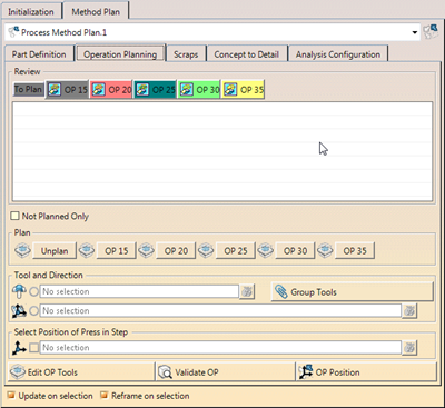
Use the Not Planned Only filter to only see not planned elements. -
Under Review, browse through the current process.
The table shows the planned element (1st column), the associated tool direction (2nd column) and the associated tool (3rd column). - Click in the first column to select the geometry.
- Click in the second column to select the direction.
A 3D compass is displayed in the graphic area if it is a cam direction. - Click in the third column to select the tool.
All elements inside the tools are selected, allowing a quick change of planning of the entire tool. - Activate Update on Selection and Reframe on Selection at the bottom of the wizard for an automatic reframe and update as you click an element.
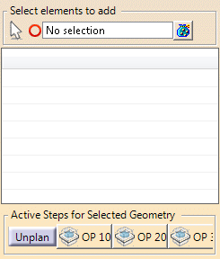
Under Plan
- Select an element to plan, either from the graphic area or from the review table.
- Click an operation below to associate it to the selected element.
- Select a planned element and a direction.
The direction is assigned to the element.
Under Tool and Direction, select the axis system that defines the tool direction.
When planning an element in a step, a tool is created by default.
For a stamped surface, it is the existing stamp tool in the target OP.
For other elements, a tool is created in the target OP.- Right-click the tool to edit its properties, to define the location of the tool (Upper or Lower die).
- Use the contextual menu to create a tool.
Still under Tool and Direction, select the axis system that defines the tool direction.
Several contextual menus are available to create an axis system, a cam direction or to optimize a direction.
See Optimizing the Stamping or Cam Direction for more information.-
Select an axis system to define the positon of the press in step.
Use the contextual menu to create an axis system.
See Defining Process Steps for more information. -
Select an element in the table and press Properties of Press Tools to define additional tools not linked to existing geometry, to further refine the concept definition of the process step.
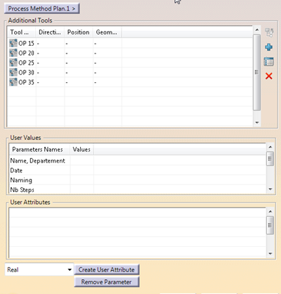
- Review all additional associated tools from the table.
- Add, edit or remove tools.
- Filter the list of tools.
- Review the parent tool or step.
- Edit user values, if available.
- Create or remove user attributes.
You can also analyze an OP or position an OP.
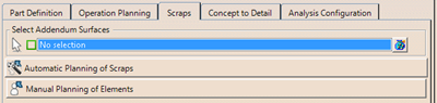
Manage Scraps
-
Select addendum surfaces to compute scraps element during the process definition.
A blank selected under Part Definition is automatically selected as addendum surface.
Use the contextual menu to create surfaces. -
Select custom elements to add and join to the result of the process step.
Select the first and the last stop that define the range within which the custom elements are joined.
Assign Detailed Geometry
-
Go to the Concept to Detail tab.
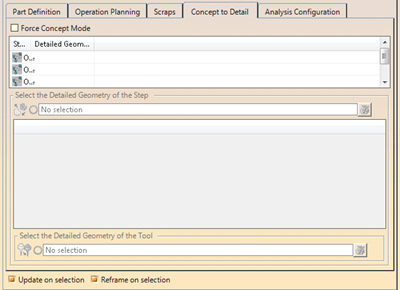
The top table displays operations and their associated detailed geometry, if any.
The detailed geometry of an operation corresponds to the resulting stage of the stamped surface at the end of the operation.
The bottom table displays the tools found inside the selected step and their associated geometry.
If selected from an outside part, the selection of elements is always forced to no link mode . -
Select an operation in the top table, then the detailed geometry to associate.
The selected geometry is displayed in the process view, under the Inputs node as Step Part Final Geometry. -
Select a tool in the bottom table, then the detailed geometry to associate.
The selected geometry is displayed in the process view, under the Results node of the tool, as Tool Geometry. -
Alternatively, select the part that contains the process proxy related to the selected step.
The step geometry and the related tool geometries are automatically retrieved from the Result Detailed Geometry geometrical set of the proxy.
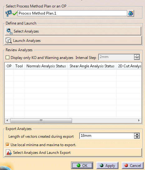
Configure Analyses
-
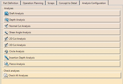
Press an analysis and enter the required values in the dialog box that opens.
-
Press Check All Analyses.
-
Select a method plan or an operation.
-
Press Select Analyses and select check boxes.
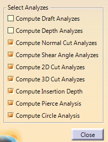
-
Press Launch Analyses.
The analysis results are displayed in the table, ready for review.
Choose Selection Options
-
Activate the required options.
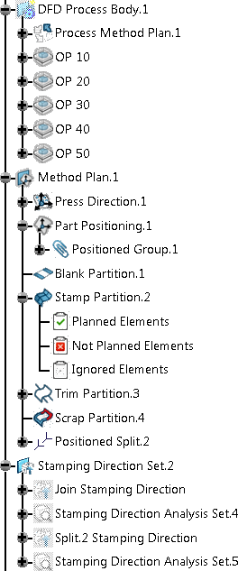
Following elements are created in the specification tree:
- A DFD Process Body that contains:
- A Process Method Plan.
- Operations.
- A Method Plan that contains:
- Press Direction
- Part Positioning
- Blank Partition
- Stamp Partition
- Planned Elements
- Not Planned Elements
- Trim Partition
- Planned Elements
- Not Planned elements
- Scrap Partition
- A Stamping Directon Set that contains:
- Join Stamping Direction
- Stamping Direction Analysis Sets
Edit mode is available.
![]()