 |
Start Process Steps
-
Click Process Step
 in the Process Definition toolbar.
If the check box
Display detailed text in dialog in Tools/Options/Mechanical
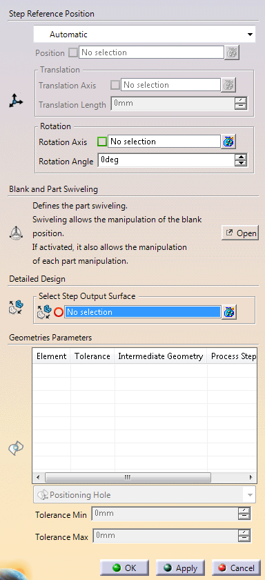
Design/Die Face Design is cleared, the dialog box looks like this:
If the
check box Display detailed text in dialog in
Tools/Options/Mechanical Design/Die Face Design is selected, the
dialog box looks like this:
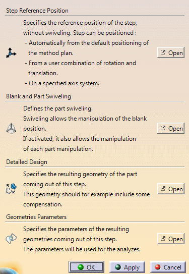
When required, click Open to access the
dialog boxes.
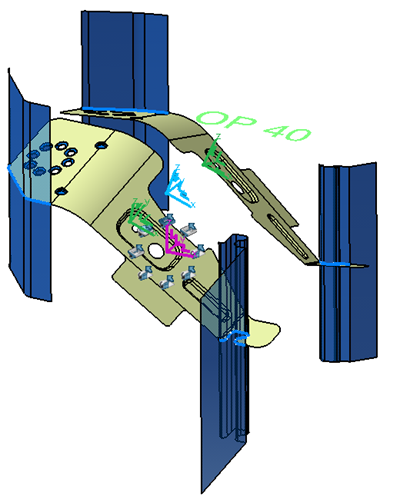
Define the Step Reference Position
A step is postioned in three steps: - The step axis
system (purple) an initial blank axis sytem position (blue)
and the initial part axis system (green) are computed from
the reference position options.
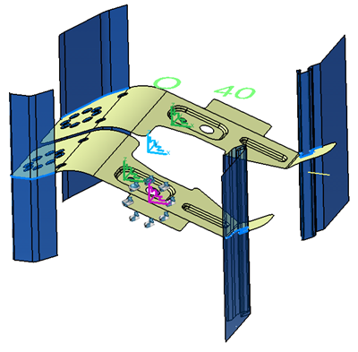
- The final blank axis sytem (blue) and an axis system for
each part are computed from the computed initial blank axis
system position, using the blank swiveling.
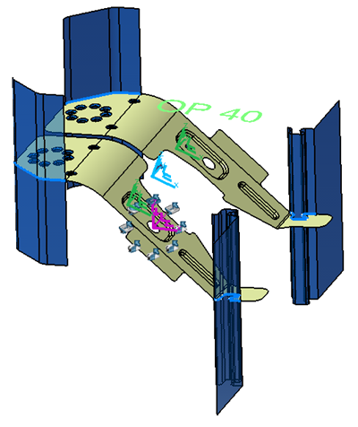
- The final positioning of each part axis system (green)
is computed using the corresponding part swiveling.
-
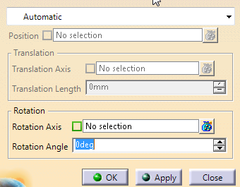
From the list, select:
-
Automatic for an automatic positioning that uses
the translation value defined in the corresponding method
plan. Additional rotation is possible.
-
Manual to use a transformation (Translation
and Rotation). Set required translation and rotation value
below.
-
Axis to use the specified axis.
|
Define the Blank and Part Swiveling
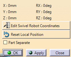
-
Define the blank and part swiveling options, by editing the
compass.
The swiveling is a local modification of axis system of either the
blank or the part, combined with the reference position. It allows
adjusting the step geometries for an easier cut or wast removal, for
example. When you open the dialog box for the first time, the compass is
on the blank axis system, thus allowing the swiveling of the blank.- Open the
Blank and Part Swiveling dialog box.
- Click Edit Swivel Robot Coordinates for a more precise
positioning of the compass.
- Click Reset Local Position to reset the swiveling.
- Select the Part Separate check box to allow the swiveling of
each part.
Use this option when there is no cutting left between
the parts, i.e. when the parts are really separated.
- Select a part axis system to define a swiveling on the part, or
the blank axis system to define the swiveling on the blank.
The compass is displayed on the selected axis system. |
Define the Detailed Design
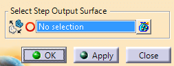
-
Define the detail design, that is the geometry of the
output parts of the step.
The geometry includes the remaining scraps
and compensation done in the detailed design and replaces the geometry
computed from the process definition.
Define Geometries Parameters
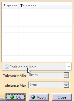
-
Specify the tolerance for the resulting geometries, to be used in analyses.
|