You can check the result in ProcessPositioning_EndP1.CATPart.
Set Design Position
Design Position defines a stamping direction
for each input, adds elements like crimps, and defines a
symmetry in the design position.
-
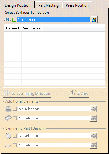
Click Part Positioning
 in the Process Part Separation toolbar.
 -
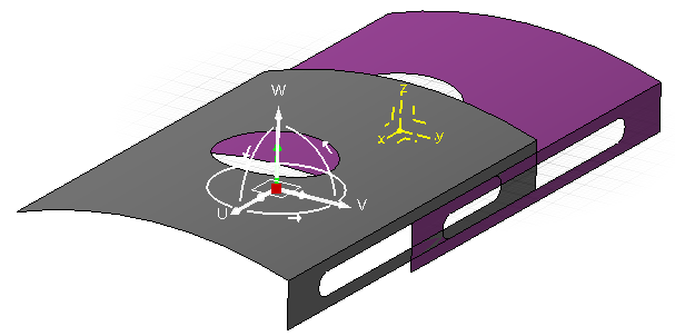
Select all surfaces to position.
- The selected surfaces (shown in grey below) are analyzed and a stamping
direction is created, on the center of gravity of the
selection, with the same Z-Axis as the part.
These are the reference surfaces and axis system. - A target axis system is created on the part axis system.
- An axis-to-axis transformation feature is created: The
reference surfaces are moved from their initial position to
the target axis system, without rotation.
The moved surfaces are the positioned surfaces (shown in purple below).
- A positioning feature is created. It is the join of all the axis-to-axis features.
- Reference surfaces are listed under
Design Position, positioned
surfaces under Press Position.
You can select them by a single click.
- The selected surfaces (shown in grey below) are analyzed and a stamping
direction is created, on the center of gravity of the
selection, with the same Z-Axis as the part.
-
Select an input surface and press
 Edit
Stamping Direction.
Edit
Stamping Direction.
See Creating the Stamping Direction for more information.
Only a correct reference stamping direction ensures that the axis-to-axis result is correctly positioned to use the Z-Axis of the part as the stamping direction. -
Select an input surface and press Z-View.
A reframe is done on the selected surface.
The Z-Axis of the stamping direction becomes the view normal. -
Add elements to the surfaces to position:
- Select a surface in the table.
- Select the elements to add in Planned Additional
Elements if planning is requested.
The elements re-use the specified positioning and appear as elements to be planned. - Select the elements to add in Other Additional
Elements if planning is not resquested.
The elements re-use the specified positioning but do not appear as elements to be planned.
-
- Select a surface as a symmetric surface.
- Select a symmetry plane.
A symmetry of the reference axis system is computed using the specified symmetry plane.
By default, the YZ plane is used.
Nest Part
Part Nesting defines the relative position of
each input, and a symmetry in the layout position.
-
Select a surface to nest, and press Edit Target Axis Coordinates.
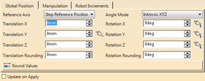
You can edit the target axis system and define a rotation of the compass.
Enter rounding thresholds and press Round Values to do so.
Select a linear element to align one axis of the compass with it.
Select a set of faces to align a direction with the mean value of the faces normal. -
Select a surface to nest, and press Z-Rotation.
A 90° rotation around the Z-Axis is applied to the surface. -
Select a surface to nest, and press Z-View.
A reframe is done on the selected surface.
The Z-Axis of the stamping direction becomes the view normal. -
Define a symmetry in the layout position for the surface to nest.
- Select a surface to nest.
- Select a symmetry plane.
A symmetry of the target axis system is computed using the specified symmetry plane.
-
If at least two positioned surfaces exists, press Compute Minimum Distances.
The minimum distances between all positoned surfaces are computed and displayed. -
Double-click the displayed distance and replace it by a target distance.
The surfaces are moved by the target distance, along the the direction that represents the minimum distance between them. -
Right-click the Compass to edit it.
Enter rounding thresholds as necessary.
Select a linear element to align one axis of the Compass with it.
Select a set of faces to align a direction using the mean value of the faces.
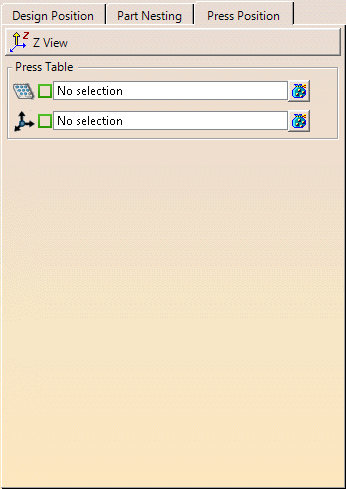
Specify the Press Table
Press Position defines the global positon of
all surfaces on the press table.
-
Press Z-View.
A reframe is done on the selected surface.
The Z-Axis of the stamping direction becomes the view normal. -
Specify the press table representation:
-
Select a face of any feature that represents the press
table.
It can be a mechanical tool or a surface.
The face is centered on the part axis, with its center normal aligned on the part Z-Axis. - Select the press table axis.
The default orientation of the press table and the reference axis for axis-to-axis transformation of the press table are specified.
-
Select a face of any feature that represents the press
table.
A Part Positioning node
is created under Method Plan.
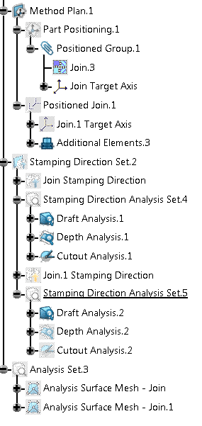
It contains
- The Positioned Surface feature with all its parameters.
- A Stamping Direction Set with a Stamping Direction feature and Stamping Direction Analysis Set.
![]()