 |
-
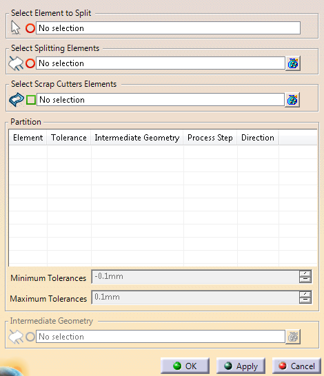
Click
Trim Partition
 in the Process Part Separation toolbar.
-
Select the
elements to split.
- A surface: The boundary of the surface is
computed. Each domain of the boundary is added as a
geometrical result.
The bigger loop (usually the outside
boundary) is the Cutting Line.
Others are typed as Positioning
Holes.
- A stamping direction: The boundary of the shape
that is the input of the stamping direction is considered.
For each part of this boundary that is associated to a tool
direction, cutting lines are computed for the external
boundary and positioning holes for the other edges.
Cutting
lines and positioning holes are computed for the other
parts, the same way.
- A surface partition: An inner join is computed
with all the partition elements, using the associated
unfolded view of each Folded Surface
geometrical result, if any.
Then, the computation is the
same as for a surface.
|
-
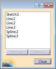
Select the splitting elements.
- 3D curves: They cut the surface boundary directly.
- Sketches: An internal extrude of the sketch is
computed, in the plane direction. Its intersection with the
surface boundary is used to cut the boundary.
- A plane and create a sketch on the selected plane from
the contextual toolbar.
The elements that split the curve are automatically trimmed at
the intersection with the boundary, only their longest part is
kept. - Each domain of the input wireframe is trimmed by
the trim elements. The kept side is either the one with the
most intersections with trim elements, or the longest side.
- The resul of the trim is a Scrap Cutter.
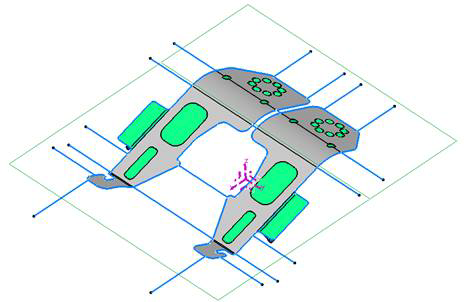
The partition of the boundary is created. Each part of the
boundary is kept, ensuring the whole part is cut by all the
cutting elements.
|
-
Select the Scrap Cutters elements
(wireframe).
Depending on the geometries inside the sketch that
defines the scrap cutters, geometries are extracted and computed with a
type (Scrap Hole or Scrap Line). This type can be changed from the
contextual menu.
Existing older trim partitions are updated to create
scrap cutters types.
-
Check the result under Partition.
- Select one element.
It is
highlighted in the work area.
- Optional: Change
its type from the contextual toolbar.
|
-
Edit the minimum and maximum tolerances of the curves as required.
For more information, see
Tools > Options.
-
Choose intermediate geometries to associate to the
selected element.
The table of results is updated.
A Partition Set is created.
such as
the blue lines and blue boundaries of green holes.

Result areas are stored under geometrical sets:
- Planned Elements (Associated to a
process action)
- Not Planned Elements (Not associated
to any process action)
- Ignored Elements (Not used by the
process).
as
- Positioning Hole
- Painting Hole
- Cutting Line
- Intermediate - name.
|