![]()
-
Click Zone
 in the Preliminary Design toolbar.
In the case you did not previously create a zone group, an information message is issued prompting you to create one.
Click OK to start the Zone Group Definition command.The Zone Definition dialog box is displayed.
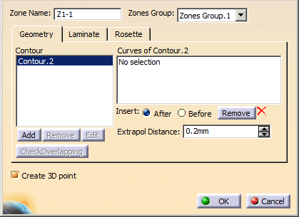
A name is proposed by default for the zone. It is editable.
In our example, we changed the name to Z1-1. -
Select the Zones Group to contain the zone.
-
Go to the Geometry tab to define a contour in the zone.
See Defining a Contour for more information.
- A zone can contain several contours.
- The contour must fully lie on the surface.
-
Optional: Click Check Overlapping to check that the zone countour does not overlap with another zone contour.
-
Select the Create 3D point check box to associate a GSD point to the zone you are defining:
This point will be used: - As anchor point for the zone name tag in the 3D view,
- As point for an automatic core sampling for each zone.
As you click OK, the 3D point will be created as the projection of the center of gravity of the zone contour onto the surface. If you re-open the dialog box, the coordinates of the 3D point will be displayed but dimmed.
It is created in the specification tree.
In most cases, you will not have to modify its coordinates. However, in some cases such as U-shaped zones, you may need to modify them:- Either by modifying the values of X, Y or Z in the specification tree,
- Or double-clicking the point in the 3D view and editing it as any GSD point.
-
Go to the Laminate tab.
Either select an existing laminate from the list,
or click New and define laminates as explained in
Defining the Composites Parameters.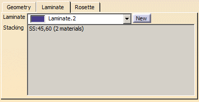
If need be, import laminates as explained in Importing a Laminate. -
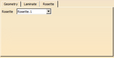
Go to the Rosette tab and select one from the list.
See About Rosette and Rosette Transfer Type for more information.
-
Click OK in the Zone Definition dialog box to create the zone.
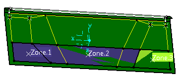
The feature is added to the specification tree, under the Zones Groups.xxx node.
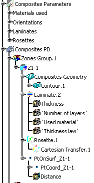
Two knowledge parameters are stored in the Laminate node. They enable you to customize the geometry used to create the zones and tapers and the associability of the zones laminate.
-
Thickness: Global laminate thickness (number of layers and material thickness)
-
Number of layers: Number of layers (addition of all layers per direction)
See also More about Materials and Laminates.
-
Perform this scenario as many times as you need to create zones.
![]()