A rosette transfer type feature is associated to the rosette feature.
This combination of features is defined in the Composites Parameters.
It is referred to as "rosette feature", and replaces the former structure where you had to select an axis system and then specify a rosette transfert type.
STEP format does not support the rosette transfer type:
- Only the axis system referenced by the rosette
feature is exported.
This axis system is retrieved at import, a rosette feature is created from it, always with the cartesian transfer type, and associated to the ply.
The rosette is an axis system positioned somewhere on the part.
- It is defined in Composites Parameters.
- Its representation in the 3D looks like this
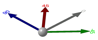
- The represented orientations depend on those defined in Composites Parameters.
- Only orientations between -180° and 180° are represented.
- Within that range, each orientation is represented by an arrow and
its value.
- There is only one arrow per orientation value.
- The color of the arrow matches that of the orientation.
- Standard Reframe On and Center tree commands are available.
- Edition of the rosette is available by double-click.
- You can define the rosette zoom behavior.
The Rosette
Transfer defines how the rosette is positioned at any location of the
reference surfaces of the Composites design.
At this location, the X-axis of
the rosette corresponds to the 0° orientation of the fiber. This information
is of high value for the designer.
- The rosette transfer type is defined during the rosette definition.
- It can be edited to allow the selection of multiple geometric entities of the specification of parameters.
- It cannot be updated, but an update error is displayed when an input is missing.
- It does not have a 3D representation.
Composites Design proposes several types of rosette transfer:
- Cartesian
- At a given point, the rosette is transferred on a plane
tangent to the reference surface.
The computation is performed only by geometric transformations of vectors.
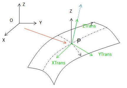
- The Z-axis of the transferred rosette is the normal at the seed point (ZTrans=N*(Orientation value)) on the reference surface (shown by the dotted blue arrow).
- The orientation value used to make the angle between the Z-axis of the initial rosette and the Z-axis of the transferred rosette is lower than 180°.
- The rosette is brought in a plane tangent to the surface at point P, using the X-axis direction of the rosette.
-
The transfer of the rosette is
computed as follows, where ^ is the vector product.
X, Y are transferred if ZTrans is not parallel to the X-axis of the rosette
YTrans = ZTrans ^ XRosette
XTrans = YTrans ^ ZTrans.
- At a given point, the rosette is transferred on a plane
tangent to the reference surface.
- Guided by Curve
The X-axis of the rosette sweeps along the guide curve (neutral fiber) to be brought to the plane tangent to the reference surface at this point.
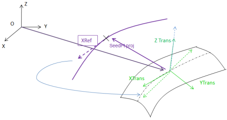
- The seed point is projected on the guide curve (projection shown by the purple arrow).
- The tangent to the guide curve is computed at the projected point. It is the XRef direction.
- The rosette is brought in the plane tangent to the surface at the point P, with respect to the XRef direction computed for the guide curve.
- The transfer of the rosette is computed as follows,
where ^ is the vector product.
YTrans = ZTrans ^XRef (on neutral fiber)
XTrans = YTrans ^ZTrans
ZTrans=N*(Orientation value), where N is the normal to the surface at the projected point (shown by the dotted blue arrow).
Two options are proposed:
- 0° guided by curve where the tangent to the guide curve is the 0° orientation, i.e. the X-axis of the rosette.
- 90° guided by curve where the tangent to the guide curve is the 90° orientation.
- External
Dedicated to external CAA users.
Cartesian vs Guided by Curve
With the Cartesian type, if the angle between ZTrans and X is small (less
than 10°), the result of the scalar product may vary a lot as in the example
below.
The reason is that the X-axis of the rosette is locally closed to the
normal of the surface at the point.
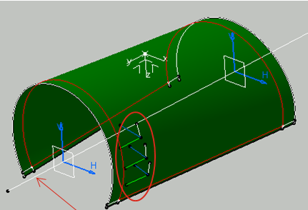
In the example below, the white axis system is the initial rosette, the
red circle shows the transferred rosettes.
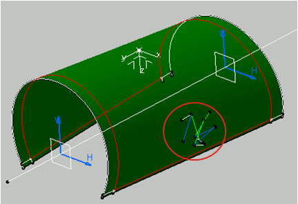
The pertinency of the rosette transfer depends on the position of the
point on the surface, and on the shape of the surface.
For U-shaped
surfaces, we recommend you use the guided by curve transfer type: The
transferred rosettes are more stable, thanks to the neutral fiber.
In the example below, the red circle shows the rosettes transferred in
relation with the neutral fiber, shown by the red arrow.
Older Models
When opening an older model, you will be asked to upgrade it to the new rosette feature. This upgrade is done in two steps:
- Migration to the extended laminates.
- Migration to the new rosette feature. This step is only available after the first one has been completed.
- A report is available at the end of the migration.
- You must migrate both Engineering and Manufacturing stackings, or mirror parts, or stackings to merge before synchronization.
The migration to the new rosette feature is done as follows:
- Only non identical rosette features are created (identical rosette features have the same axis system, the same rosette transfer type and the same transfer type inputs).
- A rosette feature is created for each axis system referenced by a Composites entity. This axis system becomes an input of the rosette.
- The rosette transfer type of this rosette feature is given by the grid panel, or the plies group, or the zone group.
- If two transfer types exist for one single axis system, one rosette feature is created for each axis system/transfer type couple.
- If a ply has a different axis system than its ply group, an additional rosette feature will be created with the axis system of the ply and the rosette transfer type of the ply group. This also applies to cut-pieces/ply, zone/zones group and virtual ply/grid panel.
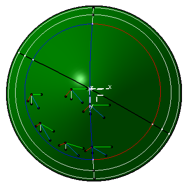
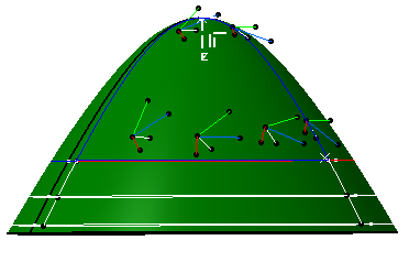
Examples
The impact of the rosette transfer is quite visible in Fiber Direction.
In the images below, the rosette is the white axis system.
The other axis
systems are transferred rosettes, at different locations on the surface.
In
those axis systems, the green line is the X-axis of the transferred rosette,
and the white line its Y-axis.
The green line corresponds to the 0°
orientation of the fiber.
In this example, the 45° orientation of the fiber
is represented by the blue line.
With Producibility, the rosette is transferred on the seed
point.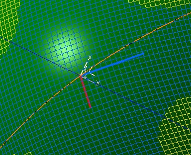
![]()