- Available in Composites Engineering Design (CPE), Composites Design for Manufacturing (CPM) and Composites Braiding (CPB).
- When working in Composites Braiding and creating plies that will be braided, start with a tubular surface and create two loop contours, one at each end (Do not create a single contour referencing two loops). These contours can be an extract of the edge at each end, or created by intersecting a plane with the tubular surface.
- You can select a curve several times to define several portions of a contour.
- As other commands create contours, the operating mode described
below applies to them as well, with possible slight differences. These
commands are:
- Zone
- Ply (and cut-piece)
- Edge of Part
- Butt Splice Zone
- No Splice Zone
Below is a scenario with the Contour command. It applies whenever you create a contour.
-
Select the support surface.
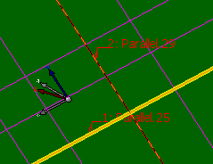
-
Select the first curve.
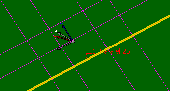
Its highlight will remain throughout the contour creation, to help you close the contour.
Its label is displayed in the middle of the curve, for a better view. -
Select the second curve.
It is highlighted.
Whenever you select a curve, its name is displayed.
If the selection is not valid, an information is added to the label.
There is a reframe on the name of the curve in the list displayed in the dialog box.
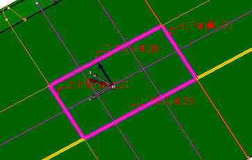
-
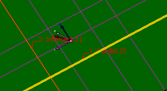
Select the third curve. This selection defines a portion of curve that can be part of a contour. This portion is highlighted.
This is only an indication, that the next selection can make irrelevant. -
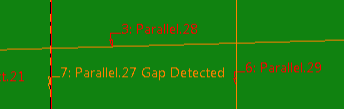
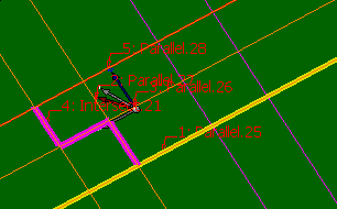
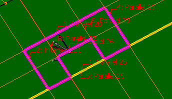
Continue the selection.
The command has detected a possible closed contour and displays it with a special highlight.
If you select another curve no longer leading to a closed contour, the special display disappears.
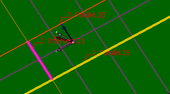
In the case below, the geometry is also too complex to define a portion of contour.
Only the first selected curve is still displayed with a special highlight.
Special highlights reappear when portions of a contour
or a closed contour are detected again.
-
Use Insert After, Before, Add and Remove to modify the order of the curves as well as the contour.
-
Define the Extrapolation distance that is the gap tolerance to support curves that do not intersect or are not connected.
- This can be the case of the output curve of slicing features.
- Extrapolation distance represents the accepted extrapolation value, i.e. curvilinear distance, for the curves that do not form a closed contour.
- It is stored in the specifications tree.
- By default, Extrapolation distance is set to 0.2 mm
-
Should you need to create the curves for the contour, right-click the curves box and create the element you need from the context menu.
![]()