and used as is to define a ply.
Each layer composing the ply is made of a material with a given orientation, e.g.

This NCF is added as a ply with an orientation and also a direction (Hand A or Hand B).
Even if used as a single material for a ply, you need to know the content of the NCF to understand and validate your design
and to transfer this information to any other process (simulation process, documentation process, manufacturing process).
Defining a Material as NCF
-
When creating the material, go to the Composites tab page of its properties and select the NCF option:
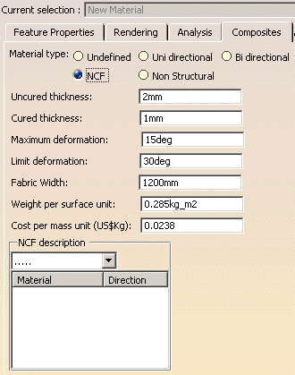
This makes the NCF description available. -
Select a material corresponding to a layer of the NCF from the list.
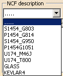
The material is added to the field below. By default, its direction is 0 degree.
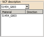
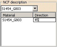
Click below Direction and enter the direction value (between 0 and 180).
-
Repeat this step for all the materials and directions of the NCF.
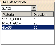
Click OK when done. -
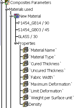
In Composites Design specification tree, NCF material (named New Material below) are displayed this way,
with the layers description directly under the node:
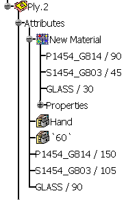
In a ply node, the Hand information is added, as well as the order of layers (depending on the Hand)
and the orientations computed from the ply orientations and those defined in the material catalog.
Those orientations are computed as follows:Ply
orientationNCF material
orientationsOrientations computed for Hand A for Hand B 0 0
45
90
1350
45
90
13545
90
135
090 0
45
90
13590
135
0
45135
0
45
9045 0
45
90
13545
90
135
090
135
0
45135 0
45
90
135135
0
45
900
45
90
13510 0
45
90
13510
55
100
14555
100
145
10
- For NCF materials, the
Attributes tab page in the Ply definition dialog box changes
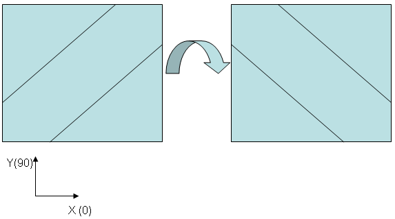
to let you choose Hand A or Hand B. - If a 45 degrees tape is flipped over (Hand A to Hand B), the
orientation is reversed by 180 degree, 45 becoming -45 degrees.
Multiple Core Samples and Producibility Inspection
NCF are ‘exploded’ for the
Multiple Core Samples and the
Producibility Inspection
to enable a complete check inside the NCF layers at the selected point.
This means that all the layers composing a core sample or being inspected
will be visible as individual layers
and provide accurate information
(especially orientation) for the same ply:
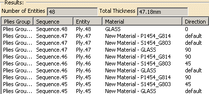
- The ply is repeated n times (n being the number of layers in the NCF),
- The material name is the concatenation of the NCF material name and of the layer material name,
- The order of the layers depends on the Hand (A or B),
- The orientations are computed from the ply orientations and those defined in the material catalog (see above).
Here is an example of a Core Sampling:
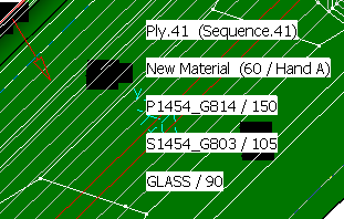
On the Fly Information
On the Fly Information displays:
- The ply orientation,
- The hand information,
- The order of the layers that depends on the Hand (A or B),
- The orientations that are computed from the ply orientations and those defined in the material catalog (see above).
Ply Exploder
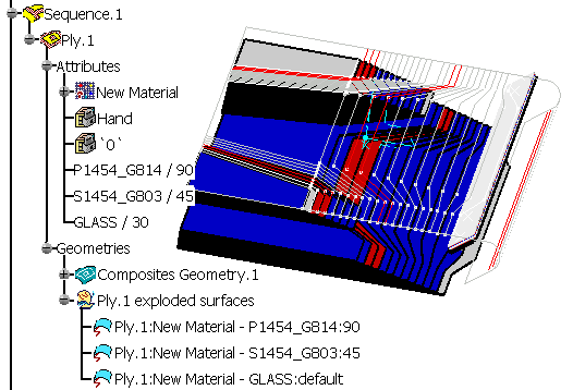
NCF are ‘exploded’ for the Ply exploder to enable a visualization inside the NCF layers of the selected ply:
- One surface is created for each layer of the NCF,
- All exploded surfaces are placed in a geometrical set aggregated under the ply or the cut-piece,
- The total thickness of the exploded surfaces for a ply or cut-piece
is equal to NCF thickness x scale factor
(i.e. the offset value for each layer of the NCF is not computed from the thickness of the layer material,
but is equal to the NCF thickness divided by n-1, n being the number of layers of the NCF), - Each surface is colorized according to the computed orientation of the layer of the NCF.
Ply Table
When exporting the ply table:
- Each individual layer composing a NCF is exported as a row in the
generated file.
This enables the visualization of exploded layers composing a ply table. - The order of the rows depends on the Hand (A or B),
- The orientations that are computed from the ply orientations and those defined in the material catalog (see above).

When importing a ply table, you cannot:
- Re-order the layers of a NCF,
- Change the orientations,
- Change the draping direction for one layer only,
- Change the name of the ply, sequence, plies group for one layer only.
All changes are imposed by the first layer (name, orientation, drapind direction, ...).
XML Export
When exporting to XML, in the material
section, the NCF is detailed to contain all layers with their own material
and orientation.
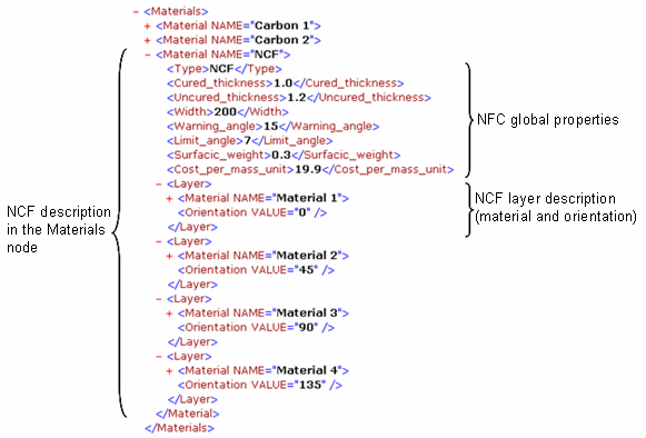
In the layers sections, depending on whether the NCF material has a
link with its constituting material,
the properties are displayed or not.
The orientation value is always exported:
- the NCF has a link with its constituting material, the properties
are displayed:
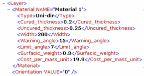
Note that the link to the NCF in the material catalog must be available when you start the XML export. - The NCF has no link with its constituting material, or the link is
not available, only the name of the material is displayed:

Symmetry
When you perform a symmetry of a plies group, the hands are switched from A to B or vice-versa.
![]()