-
Create plies from zones.
Make sure you select both Zone Group.1 and Zone Group.2. The plies are created under Plies Group.1. -
Create a plies group.
-
Click Ply
 in the Plies toolbar and select Plies Group.2 you just created.
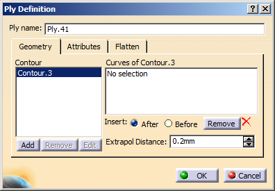
The Ply Definition dialog box is displayed.
-
Select the curves that form the contour.
See Defining a Contour for more information. -
In the Attributes tab,
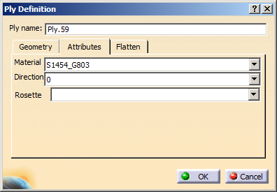
define the:from the lists.
For NCF materials, the Attributes tab page changes to let you choose Hand A or Hand B.
See About Rosette and Rosette Transfer Type for more information. -
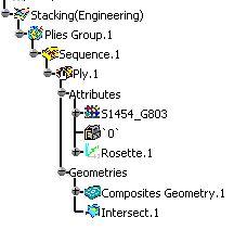
Click OK to create the ply.
The Stacking node includes the plies groups, the set of sequences (order), and for each sequence, the set of plies (containing the geometry)
-
Create three more plies, selecting the pink curves as contour on the geometry.
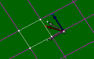
Here is the result of the plies creation.
Plies are displayed in the 3D geometry according to a color code depending on their orientation.
Starting with R18, you can no longer apply a material to a ply with the Apply Material command.
-
Right-click Plies Group.2 and select Plies Group.2 object, then Reorder children.
The sequence of plies are displayed in the Reorder Children dialog box. -
Select Sequence.63 for instance and use the up and down arrows to modify its place in the stacking.
-
Click OK.
The specification tree is modified accordingly.
-
Right-click Ply.59 and select Ply.59 object, then Change Geometrical Set.
The following dialog box is displayed, in which all the elements of the specification tree are available.
-
Select the sequence you would like to move Ply.59 to.
In our example we selected Sequence.62. -
Click OK.
The specification tree is modified accordingly.
- Note that Change Geometrical Set command enables you to move a ply from one sequence to another, whereas performing a copy/paste of a ply in a sequence creates a new ply.
- Moving a ply using the Change Geometrical Set command is taken into account when synchronizing a manufacturing document.
- The ply is highlighted in the model.
- Information is displayed in the status bar.
- Select it in the model.
- Right-click it, then select Center graph.
- To edit an existing ply, simply double-click it in the specification tree. The Ply Definition dialog box opens and you are able to modify its contours and attributes.
![]()