Both .xls and .xlsx files are supported.
You can:
-
Click Plies From Zones
 in the Plies toolbar.
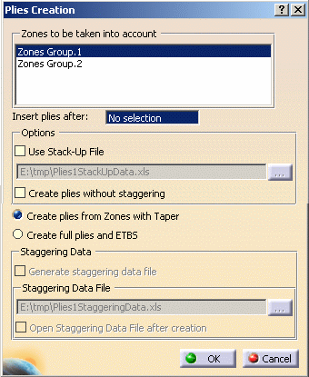
The Plies Creation dialog box is displayed.
-
Select the group of zones from which you want to create plies.
in the specification tree, simply select the sequence or the plies group where you want the plies to be inserted.
-
Use stack-up file:
If needed, import the stack-up file you may have previously created by selecting the Use Stack-Up File check box.
The import enables you to manually modify the provided stack-up and create the correct laminate.
Please note that you can only modify the plies order.
The path is the one you either defined manually or the document's path, it is automatically displayed in the field.
-
Create plies without staggering:
If needed, select the Create Plies without staggering check box to create plies without a staggered geometry. -
Create plies from zones with taper:
If needed, select the Create plies from Zones with Taper check box to create plies from zones with a transition zone. -
Create full plies and ETBS:
If needed, select the Create full plies and ETBS check box to create plies and the corresponding ETBS (edges to be staggered).
The ETBS can be used later on when using the limit contour feature to modify the plies.

An ETBS group is created for each zones group. In case you modify the contours of the zone in zones group,
the corresponding ETBS group is modified as well and an update icon is displayed on the ETBS's.

Click Update to propagate the changes in the zone group to the ETBS's.
In addition to the ETBS group, a feature corresponding to the external contour, that is, the edge of part (EOP), of the zone group is generated.
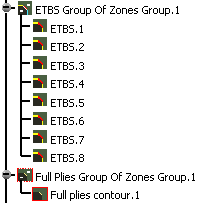
The full plies contour is the input geometry of all the plies contours.
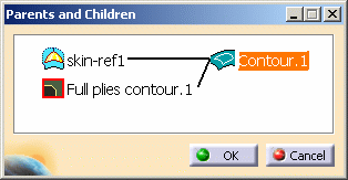
Therefore, if you modify the contour of zones group, the change is propagated to the full plies contour and the plies contour as shown in the example below. -
Select Plane.2 in the geometry.
This plane is the one on which Zones Group.1 is defined.
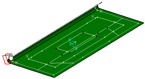
-
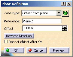
Double-click the plane to open the Plane Definition dialog box.
-
Modify the offset value to -100mm.
-
Click OK to validate.
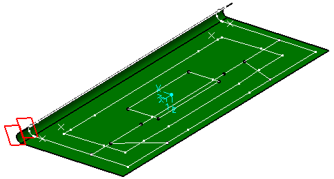
The contour of the zones group moves, so does the the full plies contour and the plies contour.
-
Select the contour of ply.1 to check it has been updated as well after modifying the zones group contour.
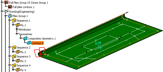
In case there is a change of surface, any modification made on the plies is kept on the new surface.
- In certain
cases, when the full plies contour is modified, the user is warned that the
ply contour will be modified accordingly.
For instance, the CATPart below is made of two zones:
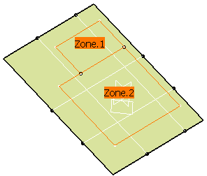
You want to modify the contour of Zone 2 as shown below:
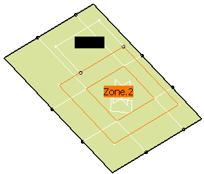
When you add the contour to Zone 2 in the Zone Definition dialog box, an information message is displayed:

An additional full plies contour is created, as well as another ply contour.
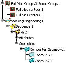
- If the ply
contour has been modified before you create an additional contour to the
zone,
the ply contour is in last position in the specification tree.
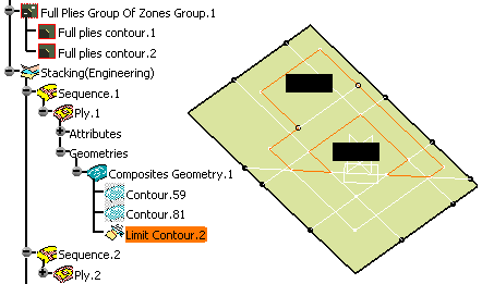
For instance, in the CATPart shown below, a limit contour has been created on Ply.1.
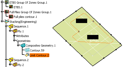
You want to modify the contour of Zone.2 by creating a contour inside the zone.
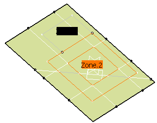
When you add the contour to Zone 2 in the Zone Definition dialog box,
an information message is displayed:

An additional full plies contour is created, as well as another ply contour.
The limit contour feature is in last position in the specification tree.
-
Generate staggering data file:
If needed, select the Generate staggering data file to create a file containing the values of each ETBS.
You can click the ... button to define the path where to store the staggering data file.
If you want to see the staggering data file content after creating the plies,
check Open Staggering Data File after creation.
- The edges to be staggered are created in an open body.
- All the created plies share the same EEOP as the Composite part.
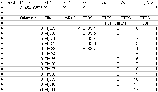
- This data file provides the
following information:
- The shapes,
- The sets of zones, direction, number of plies for each shape,
- The names of the plies for each shape,
- The set of edges to be staggered for each shape,
- The value, the step and the direction of each edge to be staggered,
-
The InvRelDir column that enables you to change the side of the material that is kept for each shape.
- The ETBS are sorted in consecutive geometrical order.
In our example, ETBS.1, ETBS.5, ETBS.4, ETBS.3 and ETBS.7 are consecutive.
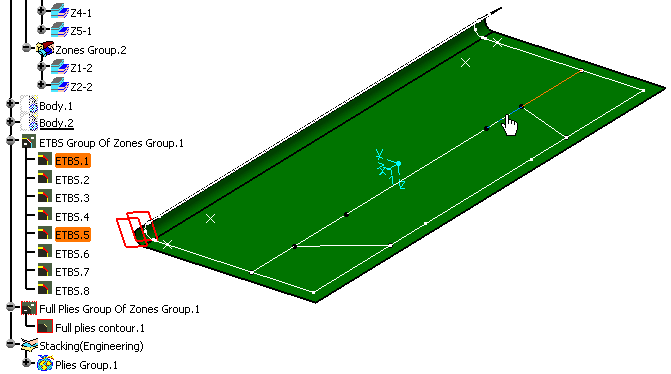
If there are two sets of ETBS that are to be used to relimit the same set of plies,
an empty space is inserted in the ETBS column between the various set of ETBS.
Inserting an empty space between each ETBS of the shape will create distinct limit contours.
Example:

There is no empty space between ETBS.1 and ETBS.2.
Their data will be read together and this will create one limit contour.
The data of ETBS.3 and ETBS.4 will also be read together and will create one limit contour.
As there is one space between ETBS.1/ETBS.2 and ETBS.3/ETBS.4 the two contours created will be distinct.
-
Click OK to create the plies with the default options selected.
- The data contained in the
Staggering Data file can then be used to create a limit contour feature for
each ply.
Refer to the Creating a Limit Contour section for more information. - The Stacking node includes the set
of sequences (order), and for each sequence,
the associated ply (containing the Attributes and the Geometry).
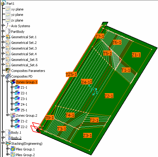
Here is the result of the plies creation from both Zones Groups.>- Result of the plies creation from Zones Group.1
- Result of the plies creation from Zones Group.2
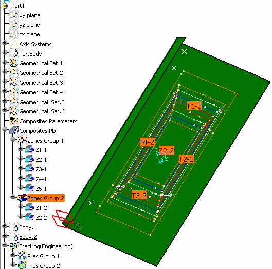
- Result of the plies creation from Zones Group.1
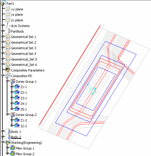
-
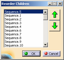
Right-click Plies Group.1 and select Plies Group.1 object, then Reorder children.
The sequence of plies are displayed in the Reorder Children dialog box. -
Select Sequence.5 for instance and use the up and down arrows to modify its place in the stacking.
-
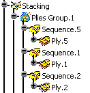
Click OK.
The specification tree is modified accordingly.
-
Right-click Ply.1 and select Ply.1 object, then Change Geometrical Set.
The following dialog box is displayed, in which all the elements of the specification tree are available.
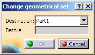
-
Select the sequence you would like to move Ply.1 to.
In our example we selected Sequence.4. Click OK.
The specification tree is modified accordingly.
- Note that the Change Geometrical Set command enables you to
move a ply from one sequence to another,
whereas performing a copy/paste of a ply in a sequence creates a new ply. - Moving a ply using the Change Geometrical Set command is taken into
account
when synchronizing a manufacturing document. - Note that the ply points to the material cache feature stored in the Composites Parameters.
- the ply is highlighted in the model;
- information is displayed in the status bar.
- Select it in the model:
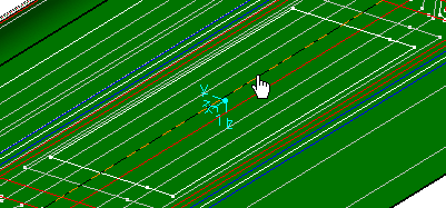
- Right-click it, then select
Center graph.
The ply and its contour are automatically expanded in the specification tree.
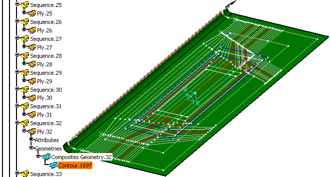
right-click the appropriate node in the specification tree and select Hide/Show 3D contour.
![]()