-
Click No Splice Zone
 in the Splicing toolbar.
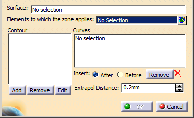
The No Splice Zone dialog box is displayed.
-
Select the surface on which the zones will be created.
Its name is displayed in the dialog box. -
Create a contour with the curves that will define the No Splice Zone.
See Defining a Contour.

The curves must form a closed contour.
-
Select the elements to which the zones apply.
- Multi-selection of entities
 is
available.
is
available. - In the multi-selection
dialog box, click
 to select entities using the Stacking Management.
- Select a stacking, plies
groups, sequences, plies.
We have selected the Stacking.
- Multi-selection of entities
-
Click OK. A No Splice Zone group is created under the Stacking, if it does not already exist,
and the No Splice Zone is created in that group.
- If you try to create 3D Multisplice, a message is displayed
- If you click Yes, the list of the splicing curves that intersect the
No Splice Zone is displayed
and you are invited to check your design. - No Splice Zone are taken into account by the
Skin Swapping command if you select
the Stacking node.
If you applied the Skin Swapping to elements under the stacking,
you can generate a Skin Swapping feature for the No Splice Zones by selecting either a zone or its group.
In this case a Skin Swapping feature will be added at the end of the Composites Geometry of the corresponding elements.
![]()