It corresponds to the engineering outer boundary of the plies.
-
Click Edge Of Part
 in the Manufacturing toolbar.
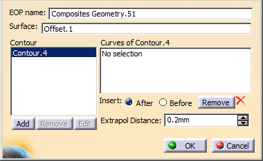
The Edge of Part definition dialog box is displayed. -
Change the EOP name as EEOP.1.
-
Select the surface on which you want to create the EEOP (Offset.1).
The Contour field is updated.
-
Create a contour of the EEOP as explained in Defining a Contour.
-
Click OK to create the EOP.
The EEOP.1 element is displayed in the specification tree under the EOPs node
and contains the closed contour.
The following task precisely explains how to define the MEOP.
![]()