-
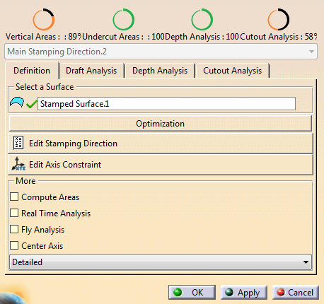
Click Stamping Direction
 in the Process Part Separation toolbar and
select a surface.
in the Process Part Separation toolbar and
select a surface.
-
Check the completion of each analysis.
Note that the Draft Analysis is done in twofold: Analysis of vertical areas and analysis of undercut areas. -
Drag the 3D Compass on the surface to optimize the stamping direction.
A specific Compass is displayed. - It shows the U, V and W axes.
- Use the small rotation arrows to quickly execute 90° rotations in the direction of the arrow.
- Translation and rotation values are displayed in the work area.
- Right-click the Compass to edit it.
Enter rounding thresholds as necessary.
Select a linear element to align one axis of the Compass with it.
Select a set of faces to align a direction using the mean value of the faces.
-
Go to an analysis tab to display editable analysis parameters and results.
For more information, see Performing a Draft Analysis, Performing a Depth Analysis and Performing a Cutout Analysis. -
Back under Definition, click Edit Stamping Direction and Edit Axis Constraint for a precise positioning of the Compass.
-
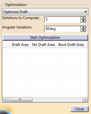
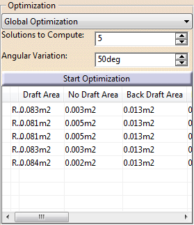
According to needs, select more analysis options:
Select faces with issues and create a Tool Direction
 from the contextual toolbar.
-
When several directions exist, select one in the list to make it current.
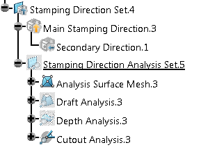
When you are satisfied with the analysis results, click OK.
A Stamping Direction Set is created. It contains
- One Main Stamping Direction
Feature (axis system).
- Secondary Direction Features (axis systems) are created below.
- One Stamping Direction
Analysis Set (for the main stamping direction), with:
- An Analysis Surface Mesh. It is a join of the analyzed surfaces that computes a mesh over them.
- A Draft Analysis feature with published parameters and a color ramp.
- A Depth Analysis feature with published parameters and a color ramp.
- A Cutout Analysis feature with published parameters and a color ramp.
- One Main Stamping Direction
Feature (axis system).
![]()