-
Click Cut Analysis
 in the Analysis toolbar.
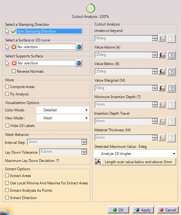
If the check box Display detailed text in dialog in Tools/Options/Mechanical Design/Die Face Design is cleared, the dialog box looks like this:
-
Select an axis system (stamping direction).
Its Z-Axis represents the cutting tool axis. -
Select the surface or 3D curve to analyze with respect to a maximum cutout angle.
If you have selected a 3D curve, select a surface.
The normal of the 3D curve with respect to this surface are retrieved.
-
To change the selection, either exit CutAnalysis and restart with another output,
or edit the mesh surface in the specification tree. -
If you have selected a 3D qcurve, select a surface.
The normals of the 3D curve with respect to this surface are retrieved. -
Select an analysis method from the list:.
- Analyze Normals: Computes the angle between the normals (Of the surface, or of the curve with respect to its support surface) and the Z Axis of the stamping direction.
- Analyze Shear Angle: Computes the shear angle (Angle between the tangents of the trim line and the tool direction).
- Analyze 2D Angles
- Projects the trim line on the plane normal to the stamping direction.
- Then computes the angle between the tangents of the projected trim lines and the Z Axis of the stamping direction.
- Analyze 3D Angles: Computes the trim angle (Angle between the normals of the trim line and the tool direction).
- Analyze Insertion Depth: Checks that the travel of the cutting tool ensures a complete cut of the material. The cam direction can be optimized according to this analysis.
-
Press Length Over Allowed Cutout Angle to display the list of areas above this value.
Select one item in the list for more details. -
Back in the Definition tab, select more analysis options:
-
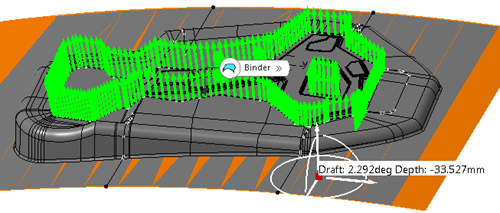
Click OK.
An Analysis set is created.
It contains a Cutout Analysis feature with a mesh of the analyzed element and the cutout
analysis.
![]()