 |
-
Click
Depth Analysis
 in the Analysis toolbar.
-
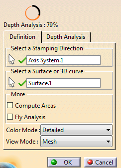
Select an axis system (stamping direction).
The Z-Axis represents the cutting tool axis.
-
Select the surface or 3D curve to analyze with respect to the
Allowed Depth.
-
Check the completion status of key indicator.
-
Go to the Depth Analysis tab.
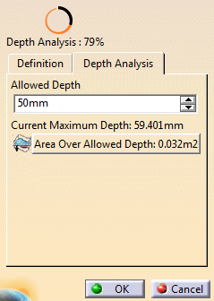 -
If necessary, modify the Allowed
Depth value.
The current maximum depth is
displayed for information.
- Press Area Over Allowed Depth to see the list of found areas.
|
Back in the Definition tab, select
more analysis options:
- Compute Areas:Computes connected areas
instead of displaying a number of faces.
- Fly Analysis:
Displays precise analysis
values while hovering over the shape.
- Color mode:
- Smooth: Displays analysis results as a
global color gradient applied to the selected shape.
Allowed values and draft settings are not used.
- Face/Edge: Displays analysis results as
colors, applied face by face on the shapes.
- Detailed: Displays analysis results as
colors, applied precisely on the shapes.
- View Mode
to display the analysis:
- Mesh
- Vectors
- Planes
- Dots
- Acute/Obtuse Dots.
|
A Depth Analysis feature is created. It contains the parameters of the analysis.
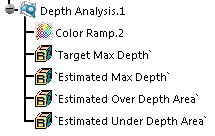
|