The information in this section will help you create and edit Spiral milling operations in your Manufacturing Program.
Click Spiral milling
![]() , then select the
geometry to be
machined
, then select the
geometry to be
machined ![]() .
.
A number of strategy parameters are available:
- Tool path style,
- Horizontal zone selection,
- in the Machining tab to define:
- the Machining tolerance,
- the Cutting mode,
- the Offset on contour,
- the Helical movement,
- to activate the Always stay on bottom option,
- or activate the Reverse tool path and the 3/5-Axis Converter options.
- in the Radial tab:
- to define the Max. distance between pass,
- to activate the Contouring pass option with its ratio,
- to activate the Along tool axis or Other axis option.
- in the Axial tab to define:
- the Multi-pass parameters,
- the Number of levels,
- the Maximum cut depth,
- the Total depth,
- the Sequencing.
- in the Zone tab to define the Max. frontal slope,
- in the HSM tab:
- to activate the High speed milling,
- to define the Corner radius.
Specify the
tool to use ![]() and
the feedrates and spindle speeds
and
the feedrates and spindle speeds ![]() ,
,
You can also define transition paths in your machining operations by
means of NC macros
![]() as needed.
as needed.
Spiral Milling: Strategy parameters
-
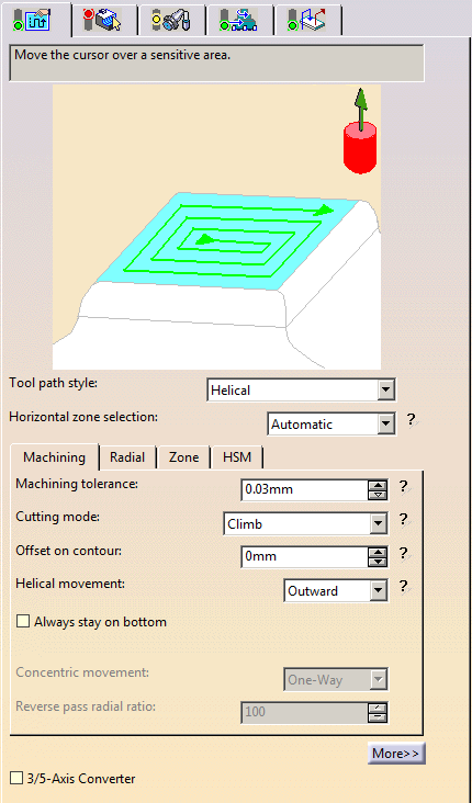
The Spiral Milling strategy parameters are distributed into 5 tabs.
By default, all 5 tabs are displayed with all their parameters.
However, most operations only require a reduced list of those parameters. -
Click <<Less button to display only those parameters.
- The Axial tab is hidden, as well as
- Reverse tool path button in the Machining tab,
- View direction is the Radial tab,
-
Click More>> button to re-display all parameters.
- You can also use the modal option
User
Interface Simplified mode in the
Tools > Options > Machining > Operation tab.
-
By default, all tabs and all parameters are displayed:
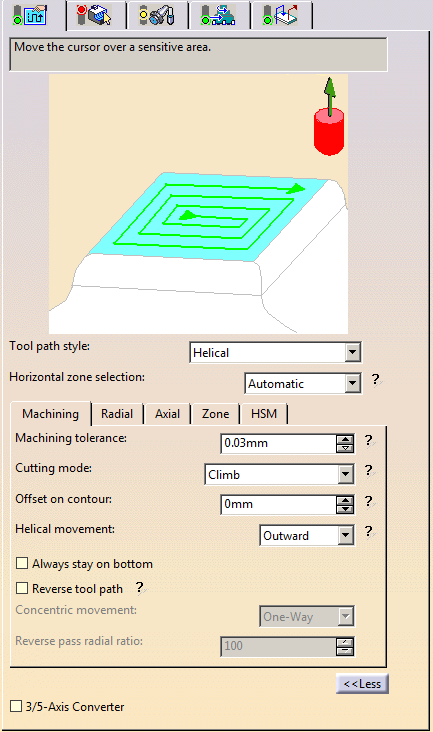
-
Click <<Less to display a reduced list of tabs and parameters:
Tool path style
- Helical:
the tool moves in successive concentric passes from the boundary of the area to machine towards the interior.
The tool moves from one pass to the next by stepping over.
The associated parameters are Machining tolerance, Cutting mode, Offset on contour, Helical movement, Always stay on bottom, Reverse tool path. - Back and forth: this cutting style is made of two kinds of
passes:
- back and forth passes,
- part contouring passes. The contouring passes can be applied before or after the back and forth passes.
The associated parameters are Machining tolerance, Cutting mode, Offset on contour, Reverse tool path.
- Helical:
-
Concentric: Builds a safe-cutting trajectory by controlling the engagement of the tool.
The trajectory created by the Concentric strategy adapts itself dynamically to ensure a safe cutting at nominal speed.
The engagement of the tool is controlled to never exceed a maximum value, even in corner areas.
This strategy is particularly recommended for hard-material milling.
In this type of material(e.g. titanium, stainless steel, ceramic, ...) the tool needs to be protected.
Other tool path styles -based on a constant distance between passes- are not appropriate because the tool load increases significantly when milling the inside of a radius.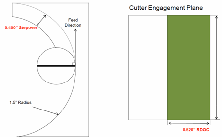
whereas the engagement is equal to the step over when milling in a straight line.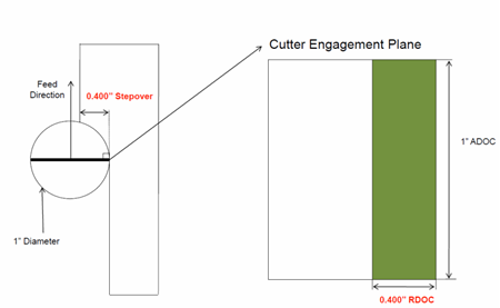
The Concentric strategy controls the tool load by modifying the distance between passes for each motion.
As a result, the tool lifetime is increased and the machining time is optimized.When the Concentric tool path style is selected:
- The HSM tab is not accessible.
- When the Horizontal zone selection is set to Manual (see below), the toggle Guide cornerization appears in the contextual menu of the contour. When it is selected, the parameter Guide radius appears.
- By default, Guide cornerization is not selected and Guide radius is set to 10mm.
Horizontal zone selection
Specifies whether the horizontal zones are detected automatically or
by means of the guide contours given by the user.
- Automatic: the surfaces that are considered to be
horizontal with respect
to the maximum angle are automatically selected for machining.
It this case, we recommend to switch to a manual detection.
- Manual: A red contour lights up in the sensitive icon.
Click it and then select the contours that will form the limit to the area you want to machine.
The selection takes account of all the surfaces inside the limit, horizontal or not.
- You can also define more than one contour.
Defining another contour inside the original contour will have the effect that only the area between
the two contours (i.e. inside one and outside the other) will be machined.- The blue contour represents the first contour,
- the black contour represents the second contour,
- and the yellow
area represents what will be machined
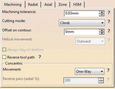
Spiral milling: Machining parameters
-
By default, or when the More>> button is pressed:
-
When the <<Less button is pressed:
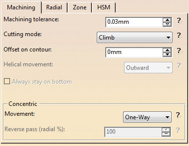
Machining tolerance
Maximum allowed distance between the theoretical and
computed tool path.
Consider it to be the acceptable chord error.
Cutting mode
Specifies the position of the tool regarding the surface to be machined.
It can be:
Offset on contour
Tool offset with respect to the contour,
- Outward: the tool path will begin at the middle of the area
to machine and work outwards.
- Inward: the tool path will begin at the outer limit of the
area to machine and work inwards.
Always stay on bottom:
This option becomes available when the tool path style is set to
Helical.
When machining a multi-domain pocket using a helical tool path style,
this parameter forces the tool to remain in contact
with the pocket bottom when moving from one domain to another. This avoids
unnecessary linking transitions.
Always stay on bottom is not active:
Always stay on bottom is active:
Reverse tool path
Hidden when the <<Less button is pressed.
Reversing the tool path means that a tool path that goes from right to
left will now go from left to right
and vice versa.
Movement
- When Movement is set to One-Way, the tool path uses the selected cutting direction.
- When Movement is set to Zig-Zag, the tool path
is optimized using both cutting directions (Climb and
Conventional).
The selected cutting mode is the main direction. Modifying it could change the trajectory.
Reverse pass (radial %)
Lets your define the
reverse radial engagement when milling in the reverse direction, that is in
the direction that is not selected as the Direction of cut.
The value is
a percentage of the main radial engagement.
A value equal to 100% keeps
the same engagement for the main and the reverse direction.
Click here for information about the 3/5-Axis Converter option.
Spiral milling: Radial parameters
-
By default, or when the More>> button is pressed:
-
When the <<Less button is pressed:
Max. distance between pass
Distance between successive passes in the tool path.
For Spiral Milling using a Back and Forth or Concentric tool path style, adds a contouring pass a the end of the back and forth path.
Contouring
pass ratio
For Spiral Milling using a Back and Forth or Concentric
tool path style, adjusts the position of the contouring pass to optimize scallop removal
(given as a percentage of the tool diameter).
View Direction
Hidden when the <<Less button is pressed.
- Along tool axis is used to compute the stepover distance, as if you were looking along the tool axis.
- Other axis is
used to compute the stepover distance, as if you ware looking along an
axis other than the tool axis.
The icon at the top of the tab for axis selection has changed and you can now select an axis
(the oblique axis in the icon) other than the tool axis for the view direction.

Other axis can only be used with a ball-nose tool.
When Other axis is active, select this check box to search for toolholder-part collisions.
Spiral milling: Axial Parameters
This tab is hidden when the <<Less button is pressed.
Multi-pass
Use the list to select the mode of input:
- Maximum cut depth and total depth:
Enter the Total depth and the Maximum cut depth
- Number of levels and total depth: 1
Enter the Number of levels and the Total depth.
- Number of levels and Maximum cut depth:
Enter the Number of levels and the Maximum cut depth.
Only two can be selected at time, you select which two via the input mode
choice.
The example below was obtained with 3 levels at a cut depth of 5mm,
but could just as easily have been obtained by:
- A cut depth of 5mm and a total depth of 15 mm,
- or a total depth of 15 mm and 3 levels.
Sequencing
Use the list to select the type of sequencing:
- By Zone:
The multi-pass machining is done zone by zone, all the levels are created on the first zone,
then on the following zone, etc...
- By Level:
the upper level is created on the first zone, then on the second zone, etc.
Then the second level is created on the first zone, then on the second, etc...
Spiral milling: Zone parameters
All parameters remain displayed in the <<Less mode.
Max. frontal slope
Available with the Automatic
Horizontal zone
selection only.
Maximum angle that can be considered as horizontal.
The angle is measured perpendicular to the tool path.
Spiral milling: HSM parameters tab
All parameters remain displayed in the <<Less mode.
High speed milling
Activates the High speed milling option
Corner radius
Rounds the ends of passes.
The ends are rounded to give a smoother path that is machined much faster.
It will be forced to this value.
Spiral Milling: Tools
The tools that can be used with this type of operation are:
- end mill tools
 ,
,
- conical tools
 ,
,
- and
face mill tools
 .
.
- with a torical cutting part, the tool path is actually computed
with an end mill tool:
in grey: face mill tool,
in blue: substitute tool,
in yellow: cutting parts.
- with a conical cutting part, the tool path is actually computed with a conical tool:in grey:
- face mill tool,
in blue: substitute tool,
in yellow: cutting parts.
- The no-cutting diameter and the cutting length of the face mill are not taken account in the computation of the tool path.
- The torical and conical parts of the tool are always taken into account as cutting parts (in yellow in the pictures).
Spiral Milling: NC Macros
General information about macros can be found in
NC Macros.
Information about the operating mode can be found in
Defining Macros.
Information about Surface Machining macro parameters can be found in
Macro Parameters.
The Clearance feedrate can be modified through its
contextual menu:
![]()
Ramping up to a plane macro is available for Approach, Retract and Linking.
Spiral Milling: Geometry
- Part with possible offset on the part (double-click the label)
- Check element with possible offset on the check element
(double-click the label).
The check is often a clamp that holds the part and therefore is not an area to be machined.
- Area to avoid if you do not wish to machine it
(light brown area in the left hand corner near the part selection area).
- Safety plane. The safety plane is the plane that the tool
will rise to at the end of the tool path in
order to avoid collisions with the part. The safety plane contextual menu allows you to:
- define an offset safety plane at a distance that you give in a dialog box that is displayed.
The new plane will be offset from the original by the distance that you enter in the dialog box along the normal
to the safety plane. If the safety plane normal and the tool axis have opposed directions, the direction of the
safety plane normal is inverted to ensure that the safety plane is not inside the part to machine.
- remove the safety plane.
Note that when an Approach/Retract macro is set to None, the safety plane is not reached.
See the Macros Parameters chapter for more information.
- Top plane which defines the highest plane that will be machined on the part,
- Bottom plane which defines the lowest plane that will be machined on the part,
- Start
points: By default, there is no user-defined start point and the
system determines automatically the start point.
When several points are selected, the system automatically performs the mapping of each selected point with the area to be machined. In each area:- when a point selected by the user exists, the system uses this point as start point,
- when more than one point selected by the user exist, the system uses one of the user point (any of the selected ones).
- the ordering of the selected points does not matter.
- Limiting contour which defines the outer machining limit on
the part.
You can also use the Part Autolimit option, with the Side to machine, Stop position, Stop mode and Offset parameters.
If you are editing a slope area,
an additional information is displayed, indicating which type of subset you
are working on.
This field is not editable (you can not go from one subset to another).
Please refer to the Basic Task - Selecting Geometric Components to learn how to select the geometry.
Appears when
invalid faces have been detected.
This message disappears when you close the dialog box or when the next
computation is successful.
![]()
Appears when invalid faces have been detected and when you have decided
to ignore them.
This message remains displayed as a warning.
Click the text to switch from one status to the other.