A number of geometry selection commands are available for selecting parts, check surfaces, drives, and so on. Please note that any hidden geometry selected using these commands is not taken into account in subsequent tool path computations. For more information, please refer to the rules described in Tool Path Computation when Hidden Geometry is Present.
The Edge Selection toolbar contains commands to help you select edges of contours when specifying geometry in machining operations. Please note that the commands in the toolbar varies according to the type of machining operation.
|
|
Display options dialog box allows you access to the following dialog box for specifying Link types, propagation domains, and propagation parameters. Link types: You can apply a global link type for managing gaps during contour selection by choosing one of the following:
- Automatic: contour selection is propagated up to a selected edge
- No link: gaps are not filled
- Line insert: a line segment is used to fill a gap
- Linear extrapolation: two extrapolated line segments are used to fill a gap
- Radial axial: for geometry in turning operations, a radial-axial transition is inserted
- Axial radial: for geometry in turning operations, an axial-radial transition is inserted.
Reverse Propagation: During edge selection, you can click this button to reverse the direction in which the following edges are to be selected.
Propagation Domains: By default, only the edges included in the current Body (or OpenBody) can be selected. You can add other bodies by clicking the Add button and selecting new bodies in the 3D viewer. You can remove selected bodies by right-clicking the Propagation Domains area and selecting Reset.
During automatic propagation, if there are more that one possible edges for selection, the best candidate is selected according to the following criteria:
- the gap between the last selected edge and the candidate edge must be less than the Maximum gap
- the angle between the tangent of the candidate edge and the tangent to the last selected edges must be less than the Maximum angle. If there still more that one candidates, the one that makes the smallest angle is preferred.
The maximum value of angle supported is 179 degree.Max Steps forward: When navigating on a belt of edges, propagation stops when the number of steps (or edges) forward is reached. In this case the label Next? appears at the end of the last selected edge to prompt a user action.
Steps Back: When resetting previous edge selections, this parameter specifies the number of edges (or steps) that will be reset.
Limiting Element: For Extend last Selected Edge, defines the length of the extension line added to the current contour.
- If you select a point as the Limiting Element, the length of the extension is defined by the projection of the point onto the extension, as described below:
A message is displayed when an extension cannot be added because the projection of the selected point coincides with the last point of the last selected element, or lies in the opposite direction.
If you select an edge as the Limiting Element, the length of the extension is defined by the intersection of the edge and the last selected element, as described below:
A message is displayed when an extension cannot be added, for example when the selected edge and the last selected element are parallel, or lie in different planes.Extension Value: For Extend last Selected Edge, defines the length of the extension line.
Deep Selection: When selected, lets you select the edges hidden by overlapping faces.
By default, Deep Selection is not selected.
Search in Plane: This check box applies to Navigate on Belt of Edges, Navigate on Edges Until an Edge , and Automatic Link Types. Once you have selected the Search in Plane checkbox, proceed as explained above for each command. The only difference is that the first two non-collinear edges you select define a plane (shown in yellow), e.g.
Or
Note:
- If you select only one edge, an error message is displayed.
- If you select more than two edges, only the last two ones are taken in account to define the plane.
- Once the plane has been defined, candidate edges are searched only in this plane, making the definition of the required contour quicker and easier:
Search in Plane is not selected:
Search in Plane is selected:
Different Facets of Edge Navigation:
There are different parameters that control the edges which would be eventually added to the contour. These deciding parameters are:
1. Link Type
2. Maximum Angle
3. Max Steps forward
4. Maximum gap
All these and a few more form the part of the options panel that is available to provide your inputs.
Some Scenario's
- Link Type = Automatic, Max steps forward = 10, Maximum Angle = 179 deg, Max Gap = 0.2mm
If 2 non-collinear disconnected edges, is selected, since the link type in the option panel is Automatic, on selecting the second disconnected link, the system will try to search for edges in the plane formed by these 2 non –collinear edges which satisfy the angle and max step forward criteria. All the edges that satisfy the criteria would be added and the system will try to connect the 2 non-collinear edges will the edges that lie in the same plane.
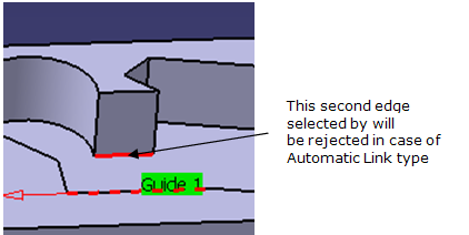
If the disconnected edges lie in different planes as shown below, then in case of automatic link type, the second edge will be rejected by the system and the next edges will be searched using the first selected edge. This is current behaviour and would continue after this enhancement too. The only big difference with the new option checked would be that the new edges would be searched lying in the plane formed by the first selected edge and next edge encountered by the system.- Link Type = No Link, Max Steps forward = 10, Maximum Angle = 179deg, Max Gap = 0.2mm
In this case, the behaviour when 2 non-collinear disconnected edges is selected would be the same as the current behaviour. No link will be created in between these edges. As the new Search in Plane option is selected, the system will try to look for edges in the plane formed by these 2 non-collinear edges and satisfying the other parameters of angle, step forward, etc.
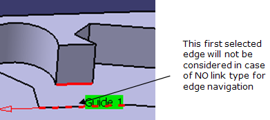
Secondly, if you select 2 non-collinear disconnected edges lying in different planes as shown below, then the first edge will not be considered for the edge navigation. This again is the current behaviour and would be maintained accordingly.
In this case, as you have selected the Search in Plane option, the edge navigation will look for edges lying in the plane formed by the second selected edge and the first candidate edge that the system encounters while searching.
- Link Type = Line Insert, Max Steps forward = 10, Maximum Angle = 179deg, Max Gap = 0.2mm
If you select 2 non-collinear disconnected edges lying in the same plane, then as the line type option is selected a line would be inserted joining the 2 non-collinear edges and then you would have to press the Navigate on Belt of Edges button in order to ask the system to look for edges. The edges which lie in the plane formed by these 2 edges would be searched for.
If the 2 disconnected edges lie in different plane as shown below, a line joining the 2 edges would be created by the system. The next edges would be searched using the second selected edge. This is the current behaviour and would be maintained accordingly.
Again as mentioned earlier too, the only different here would be that when the new check box of Search in Plane is checked, the edges would be searched in the plane that is formed by the second edge and the next candidate edge.
In case of Lathe Machining workbench (i.e. for turning operations), there are 2 more link type available; Axial Radial and Radial Axial. Here too, as in case of line insert, depending upon the link type selected, lines would be inserted to join the 2 disconnected non-collinear edges.
For all the 3 link types mentioned above, i.e. Line insert, axial radial and radial axial, lines are inserted to join the 2 disconnected non-collinear edges. These inserted lines need not be an edge in the geometry. Shortest possible distance is used as criteria for the line inserts and the main aim is to join the 2 disconnected edges.
- Link Type = Linear Extrapolation, Max Steps forward = 10, Maximum Angle = 179deg, Max Gap = 0.2mm
In case of 2 disconnected non-collinear edges lying in one plane is selected by you, linear extrapolation would be inserted maintaining the current behavior.
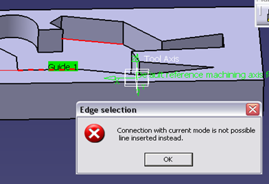
This link type doesn’t allow selecting disconnected edges that lie in different plane. Line is inserted instead of extrapolation.
After inserting a line, the behavior for searching the next edges would be similar to the line insert link type. If the new check box is selected, the edges would be searched in the plane that is formed by the second edge and the next candidate edge.Navigate on Belt of Edges allows you to select all edges that are tangent to the one you have selected.
- Select an edge and then click the icon.
Navigate on Edges Until an Edge allows you to select all edges that are tangent between start edges and a stop edge.
- Select two edges that are tangent (to give the direction of selection) and then click the icon.
- Select a third edge where you want selection to end.
Close Contour with Line.
- Select a contour or series of lines to form a contour and click on this icon. A straight line is inserted from the beginning of the contour to the end of it.
Extend Last Selected Edge allows you to add an extension line to the last selected element of the current contour, in the same direction as this element. The length of the extension line is defined either by an Extension Value or by a Limiting Element. You can repeat Extend Last Selected Edge according to your need: each time you click Extend Last Selected Edge, an extension line is added after the previous one. Added extension lines can be analyzed in the Geometry Analyzer.
Insert Lines on Gaps allows you to create a line between two points.
- Click the icon then select one point as the beginning of the line and then select a second point for the end of the line.
Reset Selection to Step Back resets the previous edge selections. The number of edges that are reset is determined by the number of Steps Back given in the Options dialog box. Reset Selection to Stop Edge resets the last edge selections up to the last stop edge. Reset All Selections resets all selections made with the Edge Selection toolbar. Accept Geometry Selections allows you to accept selected geometry and exit the selection mode. Cancel Geometry Selections allows you to refuse any selected geometry and exit selection mode.
The Face Selection toolbar and Tools Palette appear when face selection is necessary for machining operations.
The Face Selection toolbar contains commands to help you select faces when specifying geometry in machining operations. Please note that the commands in the toolbar varies according to the type of machining operation.
 |
Stiffener Selection retrieves horizontal and inclined planes to be machined as stiffeners.
- Select the required check boxes.
- Enter the values to define search ranges.
- Click
to retrieve existing values.
Navigate on Belt of Faces allows you to select all faces that are adjacent to the one you have selected.
- Select two adjacent faces and click the icon. All adjacent face are selected.
Navigate on Faces Until a Face allows you to select all faces that are adjacent between start faces and a stop face.
- Select two faces that are adjacent (to give the direction of selection) and then click the icon.
- Select a third face where you want selection to end.
Navigate on Faces allows you to select all faces which are tangent to a selected face.
- Select a face and then click this icon.
Preview the Contour allows you to highlight the contour of selected faces. Select Faces in a Polygon Trap allows you to select all faces that are situated entirely within a polygon.
- Select the icon.
- Click the places in the viewer where you want the corners of the polygon to be. Double-click to end corner definition.
Select Visible Faces in a Polygon Trap allows you to select all faces that are situated entirely within a polygon and that are visible on the screen.
- Select the icon.
- Click the places in the viewer where you want the corners of the polygon to be. Double-click to end corner definition.
Select Normal Faces lets you select faces that are:
- normal to a main axis.
- parallel or perpendicular to a face that you select as reference.
The Define Normal Faces dialog box appears when you click the icon.
The By Axis tab allows you to select all of the flat faces that are normal to a main axis.
- The Reference body is No selection. Make sure it is selected (as in the image) and click on the part to machine in the viewer.
- Choose an axis then click OK.
The faces normal to the axis you chose in the viewer are selected.- Click OK in the Face Selection toolbar to confirm your selection.
The By Face tab allows you to select flat faces with reference to a face that you choose.
- Select a part as the Reference body.
- Click in the Reference face box the select the face on the part that you want to use as reference.
- Choose whether you want to select faces that are perpendicular or parallel to that face.
- Click OK to select these faces.
- Click OK in the Face Selection toolbar to confirm your selection.
Retrieve Faces of Same Color allows you to select all faces of a given color.
- Select a face of a given color and then click the icon. All faces of that color are selected.
Note that you can define the color of a face via the Edit/Properties menu item when the face is selected.
Selection Sets allows you to select faces belonging to previously created selection sets. This action is a shortcut to the Selection Sets item in the Edit menu.
- Click on the icon and select the selection set you want to use in the displayed dialog box.
- Press Close.
Multi-selection of Face allows selecting a face more than once during drive element selection in Multi-axis Flank Contouring operations. Reset All Selections.
- Click the icon to reset all selections made with the Face Selection toolbar.
Accept Geometry Selections allows you to accept selected geometry and exit selection mode. Cancel Geometry Selections allows you to refuse any already geometry and exit selection mode.
The Tools Palette toolbar contains commands to help you multi-select face elements. See Using the Selection Traps for more information.
|

Selection Trap on Geometry allows you to start the trap on a specific element and not on an empty space as this is the case for the other selection trap modes. 
Rectangle Selection Mode lets you select objects by drawing a rectangular trap. Drag using the left mouse button to define the rectangle until the objects you want to select are completely inside. Then, release the mouse: the objects are highlighted to indicate they have been selected. 
Intersecting Rectangle Selection Mode lets you select objects by drawing a rectangular trap just like Rectangle Selection Mode but this time, any objects intersected by and inside the trap will be selected. 
Polygon Selection Mode lets you select objects by drawing a closed polygon. Drag using the left mouse button to define the polygon around the object to be selected, then double-click to close the polygon. 
Free Hand Selection Mode lets you select objects by simply drawing a paint stroke across them. Drag using the left mouse button to create the paint stroke: any objects crossed by the paint stroke will be selected. 
Outside Rectangle Selection Mode lets you select objects by drawing a rectangular trap just like Rectangle Selection Mode but this time, any objects located strictly outside the trap will be selected. 
Outside Intersecting Rectangle Selection Mode is different from the Intersecting Rectangle Selection Mode since it lets you select objects intersecting the rectangular trap as well as objects located outside the rectangular trap. Drag using the left mouse button: any objects out of the trap or intersecting the trap are selected.
In some cases when automatic propagation is interrupted, a label appears at the extremity of the last selected edge. For example:
Each face of a Body is linked to the container which is immediately above it in the specification tree. This container is either a PartBody or a Geometrical Set. It is highlighted in the specification tree when you pass the cursor over the face.
This can be important when a face linked to a body is selected in an operation. It is the container that is taken into account for machining and tool path computation.