To edit a macro:
- in graphic mode, double-click a macro path or a geometry element to modify it. Double-click a parameter label to display the edition dialog box to modify the value of this parameter only (since those dialog boxes are standard edition boxes, they are not shown below).
- In numeric mode, type the required value in the field. Use the interrogation mark to launch the graphic help.
- The current macro is displayed in violet.
-
The parameters dialog box can also be launched by double-clicking a portion of the path in the viewer.
-
You can also double-click a label in the viewer. This will start the Edit dialog box of the corresponding parameter.
- The graph displayed in the viewer of the dialog box is a
generic representation of a macro mode.
It is not the true representation of the macro you are using or defining.
To check the result of you settings, click Tool Path Replay.
Dialog box in the graphic
method:
Dialog box in the
graphic method, using the Build by user macros:
Dialog box in the numeric mode:
Place your cursor on a portion of the macro path.
Right click to display the contextual menu.
- Delete and Insert are available for the Build by user macros.
- The parameters dialog box can also be launched by double-clicking a portion of the path in the viewer.
- can also double-click a label in the viewer. This will
start the Edit dialog box of the corresponding parameter.
The graph displayed in the viewer of the dialog box is a
generic representation of a macro mode.
It is not the true representation of the macro you are using or defining. To
check the result of you settings, press Replay.
- Approach,
- Retract,
- Linking Retract,
- Linking Approach,
- Clearance,
- Between passes (not available for Spiral Milling, Pencil),
- Between passes Link (not available for Spiral Milling,
Pencil, ZLevel).
Between passes Link corresponds to the highlighted portion of the path below:
 |
- In the Macro column, you find the type of the macro,
- In the Name column, you find the name of the macro,
- In the Mode column, you find the machining mode of the macro.
By default, the application has affected a machining mode to each macro.
To affect another machining mode to a macro, select the macro line in the
Macro Management frame,
then select a machining mode in the Mode list, for examples:
For Approach, Retract, Between passes:
- Along tool axis,
- Along a vector,
- Normal,
- Tangent to movement,
- None,
- Back,
- Circular,
- Box,
- Prolonged movement,
- High speed milling (not available for Sweep Roughing, Spiral Milling, Pencil),
- Ramping up to plane (Spiral Milling),
- Build by user.
For Linking Retract, Linking Approach:
- Along tool axis,
- Along a vector,
- Normal,
- Tangent to movement,
- None,
- Back,
- Circular,
- Box,
- Prolonged movement,
- High speed milling (not available for Sweep Roughing, Pencil,)
- Ramping up to plane (Spiral Milling),
- Defined by Approach/Retract,
- Build by user.
For Clearance:
- Optimized,
- Along tool axis,
- Perpendicular to safety plane (not available for ZLevel).
For Between passes Link (not available for Pencil):
- Straight,
- High speed milling (not available for Sweep Roughing),
- Prolonged movement,
- Defined by Approach.
Definition
Along
tool axis
The tool moves along the tool axis for a given
Axial motion Distance,
In graphic mode, double-click the line to edit the Axial motion,
In numeric mode, type the Axial motion Distance value.
Along a
vector
The tool moves along a vector (line motion) for a given
Distance,
In graphic mode:
-
double-click the violet line to edit the Distance along the line motion,
-
double-click the green line to edit the direction.
In numeric mode:
-
type the Distance value.
-
click Direction to edit the vector direction.
Normal
The tool moves in a direction perpendicular to the surface being machined (Perpendicular
motion), for a given Distance,
In graphic mode, double-click the violet line to edit the distance in the
Perpendicular motion,
In numeric mode, type the Perpendicular motion Distance.
Tangent to Movement
The tool motion is tangent at its end to the
rest of the tool path and is of a given Distance
with a vertical
angle
and a horizontal angle.
In graphic mode, double-click the violet line to edit the Distance
and the Vertical angle and
Horizontal angle.
In numeric mode, type the
Distance and the Vertical
angle and Horizontal
angle.
None
No approach nor retract macro is applied.
Note that when this macro is
selected on Approach or Retract, no Link to Safety
Plane is added, as shown below.
If you require a Link to Safety Plane, select Along tool axis
with an axial motion Distance value equal to 0 mm. This is what
you will get:
(This is not available with an isoparametric machining operation.)
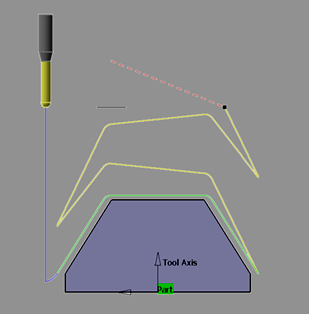
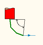
Back
The tool doubles back like an arrow above the cutting tool path (Back
motion).
You can define this type with a Distance
and a Height.
In graphic mode, double-click the violet line
to edit the Distance and the Height
In numeric mode, type the Distance
and the Height
When you type a Distance higher than
the cutting tool path to which the macro refers, a tool path Along Tool
Axis is added, its length being equal to the difference between
Distance and the length of the cutting tool path.
Circular
The tool moves towards/away from the part in an arc (Circular
motion).
The Circular macro parameter conventions for:
- Radius
Consider the Spindle Axis System as shown below:
The line OC can be a tool path or a macro before the Circular motion macro. The positive (+ve) radius positions the arc (in pink color) towards center A and to the left of the line OC. The negative (-ve) radius positions the arc (in green color) towards center B and to the right of the line OC.
Note: The arcs produced are always smooth with respect to the preceding line.
- Angular Sector with Positive Radius
Consider the Spindle Axis System as shown below:
The positive (+ve) angular sector with positive (+ve) radius gives the direction of circular arc:
- Anticlockwise for Retract macro
- Clockwise for Approach macro.
Note: For a positive (+ve) radius, all negative angles are converted to equivalent positive (+ve) angle. The above image shows an example for positive (+ve) 150 degrees and negative (-ve) 210 degrees, here negative (-ve) 210 is equivalent to positive (+ve) 150. Hence the arc produced in both these cases is essentially the same (pink arc).
- Angular Sector with Negative Radius
Consider the Spindle Axis System as shown below:
The negative (-ve) angular sector with negative (-ve) radius gives the direction of circular arc:
- Clockwise for Retract macro
- Anticlockwise for Approach macro.
Note: For a negative (-ve) radius, all positive angles are converted to equivalent negative (-ve) angle. The above image shows an example for positive (+ve) 90 degrees and negative (-ve) 270 degrees, here positive (+ve) 90 is equivalent to negative (-ve) 270. Hence the arc produced in both these cases is essentially the same (pink arc).
The parameters that you can set are:
- For the Circular motion:
- the Angular sector,
- the Angular orientation,
- the Radius,
- the Angular sector,
- The Axial motion Distance
In graphic mode:
-
double-click the arc (yellow line) to edit the Circular motion:
-
double-click the violet line to edit the Axial motion Distance.
In numeric mode, type the Angular sector, the Angular
orientation, the Radius and the Axial motion Distance.
Important:
|
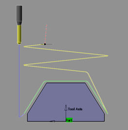
Ramping
The tool follows a slope defined by the ramping angle.
The parameters to define are the Axial motion Distance and the
Ramping angle.
In graphic mode:
-
double-click the violet line to edit the Axial motion Distance:
-
double-click the yellow line to define the Ramping angle:
In numeric mode, type the Ramping angle and the Axial motion
Distance.
Ramping up to plane
The tool follows a slope defined by the ramping angle up to a plane.
The parameters to define are the Angle and the plane.
In graphic mode, double-click the angle to define it:
and click the plane to select one.
In numeric mode, enter the angle:
It is no longer allowed to go down when the tool path does so:
- former behavior:
- new behavior, that avoid plunges into the material:
Recompute existing processes that contain Machining Operations with Ramping up to plane macros to apply this new behavior and modify the tool path accordingly.
The Machining Operations impacted are:
- Sweep Roughing,
- Sweeping,
- 4-Axis Curve Sweeping,
- Pencil,
- Contour-driven,
- Spiral Milling,
- Multi-Axis Spiral Milling,
- Multi-Pockets Flank Contouring.
Circular or ramping
The tool uses either circular or ramping
mode depending on whichever is best adapted to the part being machined.
The Circular or ramping motion is defined by
-
Angle
-
Angular orientation
-
Radius
-
Ramping angle
The Prolonged motion is defined by
- Length
- Angle
In graphic mode:
- double-click the
orange line to edit the Axial motion Distance
- Double-click the inclined yellow line to edit the Prolonged motion:
- Double-click the arc to edit the Circular or ramping motion:
In numeric mode, type:
- the Angular sector, Angular orientation, Radius and Ramping angle for the Circular or ramping motion,
- the Length and Angle for the Prolonged motion and
-
the Axial motion Distance.
For ZLevel, the Angular sector cannot exceed 180 degrees.
Box
The tool moves across the diagonal of an imaginary box (Box
motion), either in a straight line or in a curve (Linking
mode).
The Box motion is defined by:
- the Distance along
the tangent
- the Distance
along the tool axis (can be a negative value),
- the Distance
along the normal axis,
- the direction of the box diagonal that is defined by whether you want to use the normal to the left or the right of the end of the tool path (Side of normal axis). Left or Right is determined by looking along the tool path in the direction of the approach/retract.
- the Linking mode (Curved or Straight).
The Axial motion Distance is the distance that the tool will move in once it has crossed the box.
- Distance along the tangent
- Distance along the tool axis
- Distance along the normal axis
In graphic mode:
- double-click the violet line
to edit the Axial motion Distance:
- double-click the arc (yellow line) to edit the Box motion:
In numeric mode
- type the values of the Distance/tangent, Distance/tool axis, Distance/normal axis, and of the Axial motion Distance.
- choose from the list which side of the normal axis will determine the direction of the diagonal of the box.
- select a Linking mode (Curved or Straight).
Prolonged Movement
The
tool moves in a straight line that may slant upwards.
The Prolonged motion is defined by:
- the Distance,
- the Vertical angle,
- the Horizontal angle,
The Axial motion is defined by the Distance.
The advantage of this mode is that collisions are automatically detected.
In the event that a possible collision is detected, the angle will be
adjusted to avoid collision. If the angle cannot be adjusted (because of the
shape of the part, for instance), the length of the prolongation will be
automatically adjusted to avoid collision.
In graphic mode:
- double-Click the violet
line to edit the Axial motion Distance
- double-click the yellow line to edit the Tangent motion:
-
In numeric mode, type the Distance, the Vertical angle, the Horizontal angle and the Axial motion Distance.
The parameters are:
- Axial motion Distance,
- Transition radius which is the radius of the arc that goes to the
pass.
- Discretization angle which is a value which, when reduced, gives
a smoother tool path.
- Transition angle which is the angle of the arc that goes to the
pass.
Its value varies between 0 and 180 degrees.
By default, it is set to 180 degrees.
- The Machining Operations
impacted are:
- Sweeping,
- 4-Axis Curve Sweeping,
- Pencil,
- Contour-driven,
- Spiral Milling,
- Multi-Axis Spiral Milling,
- Multi-Pockets Flank Contouring.
- The Machining Operations
impacted are:
In graphic mode:
-
double-click the violet line to edit the Axial motion Distance:
-
double-click the green arc to edit the High Speed Milling motion:
In
numeric mode, type the Radius, the Discretization angle
and the Transition angle defining the High Speed Milling
motion, and the Axial motion Distance.
Defined by Approach/Retract,
Defined by Approach
The
macro used for the Linking Retract, Linking Approach or Between passes Link
is that used for the Approach or the Retract.
Build by user
Available in graphic mode only.
You can create a machining path by adding
several predefined macros.
The current one is colored violet.
If necessary, you can double-click:
- the line representing the macro to edit its parameter,
- the associated geometry representation to edit this geometry.
We have listed below:
- the icons,
- the name of the macros,
- the representation of the macros,
- the corresponding edition dialog box.
![]() Add Tangent motion
Add Tangent motion
![]() Add Circular motion
Add Circular motion
see
also Circular
Surface Machining and Multi-Axis Curve Machining and Flank Contouring:
Multi-Axis Machining (except for Curve Machining and Flank Contouring):
With:
Normal to last tool axis:
Normal to part surface:
![]() Add circular or
ramping motion
Add circular or
ramping motion
See also
Circular or Ramping
![]() Add ramping motion
Add ramping motion
Surface Machining:
Multi-Axis Machining:
![]() Add motion
perpendicular to a plane
Add motion
perpendicular to a plane
Click the plane on the icon, the dialog box disappears.
Select a plane in the graphic area.
![]() Add Axial motion up
to a plane
Add Axial motion up
to a plane
Click the plane on the icon, the dialog box disappears.
Select a plane in the graphic area.
![]() Add distance along a
line motion
Add distance along a
line motion
See also
Along a vector
Note that in ZLevel, this macro can be created alone with
Add axial motion only.
![]() Add normal motion
Add normal motion
See also
Normal
Surface machining:
Multi-Axis
Machining:
![]() Add back motion
Add back motion
See also
Back
![]() Add circular within a
plane motion
Add circular within a
plane motion
![]() Add box motion
Add box motion
See also
Box
![]() Add prolonged motion
Add prolonged motion
see also Prolonged movement
![]() Add high speed milling
motion
Add high speed milling
motion
See also
High speed milling
![]() Add motion to a point
Add motion to a point
Available in ZLevel - build by user mode.
Click the point on the icon, the dialog box disappears.
Select a point in the graphic area.
Note that this macro can be created alone with Add axial
motion only.
![]() Enable
5-axis simultaneous motion
Enable
5-axis simultaneous motion
Not available after a tool axis motion, a ramping motion and a helix
motion.
You have to define a direction:
This macro rotates the tool in macro paths and minimizes machine jolts
by generating a 5-axis simultaneous motion on the next combined
motion.
Combined with a tangent motion:
The tool axis is interpolated between the defined direction and the
current macro tool axis, according to the Max discretization angle
of the operation.
![]() Keep machining feedrate
Keep machining feedrate
Applies the
machining feedrate to all the macro paths.
Straight
The tool goes directly to the next path.
Clearance
For all clearances, if no safety plane is defined, the safety plane is the upper point of the part.
- Optimized
This means that if no obstacle is detected between two passes, the tool will not rise to the safety plane (because it is not necessary) and the operation will take less time. In some cases (where areas of the part are higher than the zone you are machining and when you are using a safety plane), the tool will cut into the part. When this happens, choose another clearance mode.
In both modes, you can only edit the Distance parameter by double-clicking the label.
-
Clearance Along Tool Axis
The tool moves up to the defined safety plane along the tool axis.
- Perpendicular to
Safety Plane
The tool moves up to the defined safety plane along an axis perpendicular to the safety plane.
Options
Cornerized clearance with radius
Select this option to create a cornerized clearance and enter the value
of the corner radius.
Smooth tool axis moves
When selected, if the approach and the retract axes are different,
additional points are added on the rapid motion in order to smooth the
transition path.
The tool axis is interpolated, according to the Max discretization
angle.