|
This task shows you how to save in STEP formats the data contained in a CATPart or CATProduct
document. STEP formats are used for the data exchange between the Assembly
workbench and other CADCAM software products. Saving your assembly in STEP
format comes down to gathering assembly data into one file.
The assembly structure and the geometry (in compliance with the STEP format)
are saved. If you do not have any STEP license, you can nevertheless save
the assembly structure in STEP.
You can export:
- CATProduct documents (resulting in STEP AP203/AP214/AP242 files in
compliance with Part 44)
- CATShape documents. However, if you
re-import a STEP file made from a CATShape, you will create a CATPart.


See also:
CAx Implementor Forum
http://www.cax-if.de
http://www.cax-if.org
You can find further information in the Advanced Tasks:
Statistics about each import operation can be found in the
report file and the error file created.
The table in What about
the elements you export ? provides information on the entities you can
export. |
 |
Check the
license requirements for STEP! |
 |
-
Go to the Tools > Options >
Compatibility > STEP tab.
Under Application Protocol (AP), select the required
Application Protocol from the list,
and click OK.
-
Open the CATPart or CATProduct document to be saved in
STEP.
-
When the document is open, select the File > Save
As... command.
-
Specify the name you want to give to the STEP file in the
File name: field.
|
|
|
-
Select STEP (*.stp), STEP (*.stpZ), STEP (*.stpx) or STEP (*.stpxZ) from the
Save
as typelist type.
Z stands for compressed files, x for STEP XML
files.
-
Click the Save button to confirm the operation.
For a CATProduct, there is one conversion operation for each CATPart
document referenced by the product.
| A progress bar is displayed for each conversion operation. |
 |
You can use the Cancel button to interrupt the transfer at any
time.
The current conversion operation is then interrupted (after the
processing of the current independent entity) and the partial
conversion already performed is saved in the STEP file. |
-
Open the .stp file you will see that the file header
contains the following information:
- the file name
- the date of creation (with the year expressed in four digits
meaning that your STEP data will be year 2000-compliant)
- the V5 version used for the conversion.
Note that the file description field is not written in the header
of STEP XML files.
|
|
| |
Several export options can be customized:
-
Detailed report (not yet completely available for export),
-
Validation Properties,
-
Groups (Selection Sets),
-
3D annotations,
-
Composites,
-
User Defined Attributes,
-
Application Protocol (AP),
-
Exact geometry as, to export data as exact or tessellated,
-
Units, to choose the unit of the exported file,
-
Show/NoShow, to export all entities or only visible
entities,
-
Header of the STEP file,
-
Assemblies,
to use external references, thus reducing memory problems.
|
|
 |
| |
Exchanging 3D Geometry
One of the current primary uses of the AP214/AP242 Standard is to exchange
geometry. The STEP Interface enables users to exchange the B-REP of exact
solids. The exchange process is based on AP214/AP242. This application protocol is
very similar to AP203 as it shares the same resources expressed in the PART
42.
Please remember:
- You can export the bodies (volumes, shells and faces) of CATPart or
CATShape documents (resulting in STEP AP203/AP214/AP242 files in compliance
with Part 42).
- The export of Shells occurs with no limitation and all the structure
information can be recovered.
- When a CATProduct document is exported the geometry/topology of the
CATPart or CATShape or .model documents is also stored in the .stp file.
- You export the final construction object, i.e. the whole
specification tree and its history up to the feature at the bottom of
the specification tree and not the current feature. Delete unwanted
features located after the one you want to export.
Exchanging Visual Presentation of 3D Geometry (Exact or Tessellated)
The STEP interface
enables users to exchange visual presentation of exchanged geometric
elements.
Please remember:
- Layers:
- Layers on exported entities are supported.
However, since
V5 does not support layers on tessellated geometry, export of layers on
tessellated geometry is not possible.
- The visibility of layers is not taken into account: all layers are
handled in the same way, event if filters are defined.
- The V5 number of layer is mapped with STEP attribute
PRESENTATION_LAYER_ASSIGNMENT.ID
- Color:
- Colors are not exported with AP203 edition1.
- When the color of a given face is different from the
color of its solid, an entity OVER_RIDING_STYLE_ITEM is created in the
STEP file, and the face keeps the overriding color.
- STEP limitation with assemblies: since attributes can not be set on
instances of components, the color of instances are not taken into
account.
- Lines:
- V5 handles 7 types of line whereas STEP proposes 5 types only. The
mapping is the following:
| V5 line type |
STEP line type |
 |
Continuous |
| Dotted |
| Dashed |
| Chain |
| Chain double dash |
| Dotted |
| Chain |
- Thickness is supported at export.
- Points:
- Point styles are mapped as follows:
| STEP point style |
V5 point style |
| cross, triangle |
 |
|
plus |
|
| circle |
|
| square |
| asterisk |
|
| dot |
- Points belonging to a sketch:
A point belonging to a sketch is exported only if the sketch contains
only points.
|
|
|
Tessellated and Exact Geometry
V5 data are can be exported to STEP tessellated geometry as
follows:
- Solid geometry is exported to a STEP file as
TESSELLATED_SOLID, and TESSELLATED_EDGE for the edges.
- Surfacic geometry is exported as TESSELLATED_SHELL,
and TESSELLATED_EDGE for the edges.
- Wireframe geometry is exported as TESSELLATED_WIRE
or TESSELLATED_VERTEX.
- Structured tessellations are supported. For example,
a structured cgr representing a keyboard is exported to
a STEP file as a structured STEP tessellation (the
geometry of all the keys of a given type is represented
as a single solid).
- By default, exact geometry is exported as B-rep exact
geometry.
With AP242 ed1, you can also export exact
geometry as tessellated geometry.
- When the geometry is exported to STEP (all Assemblies
options) the visualization representation referenced by a
product are exported as STEP Tessellated Geometry.
- Validation properties are suported when requested.
- Transparency is supported by tessellated geometry.
- Transparency is supported by exact
geometry (solids, shells and faces).
The transparency of
a face of a solid can be overloaded and is kept in the STEP
file.
However, the transparency of an instance cannot be
overloaded (It is ignored at export).
See
Exact geometry as for more information.
|
|
|
Composites Data
When the
option is selected:
- Only the engineering stacking is taken into
account.
- Preliminary design data are not
supported.
- Only materials used by the engineering
stack are supported.
- Flat pattern is not supported.
- Analysis and simulation are not
supported.
|
|
|
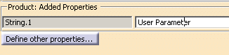
User Defined Attributes
The User Defined Attributes taken into account are:
- the Product: Added Properties (defined for a CATProduct
or a CATPArt),
- The user parameters defined at the PartBody level (i.e. associated
to the solid it contains).
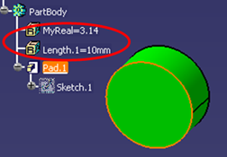
- The user parameters defined at surface feature level, contour
feature level and point feature level.
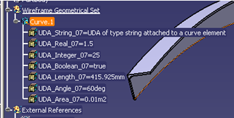
For each User Defined Attribute, STEP preserves:
- the name,
- the value (the formula is lost),
- the type of the parameter (string, integer, real, boolean),
- the measure (when managed by STEP),
- the unit (when managed by STEP),
-
the association to a CATProduct or a PartBody.
The mapping is as follows:
| Real |
NUMERIC_MEASURE (AP214) or
REAL_REPRESENTATION_ITEM (AP203 ed2/AP242 ed1) |
| Integer |
COUNT_MEASURE (AP214) or
INTEGER_REPRESENTATION_ITEM (AP203 ed2/AP242 ed1) |
| String |
DESCRIPTIVE_REPRESENTATION_ITEM |
| Boolean |
String with value TRUE or FALSE and an additional
meta-attribute specifying that the string UDA is a Boolean
(AP214)
or BOOLEAN_REPRESENTATION_ITEM (AP203 ed2/AP242 ed1) |
| Length |
MEASURE_REPRESENTATION_ITEM with name |
| Area |
MEASURE_REPRESENTATION_ITEM with
name |
| Volume |
MEASURE_REPRESENTATION_ITEM with name |
| Mass |
MEASURE_REPRESENTATION_ITEM with name
MASS_MEASURE (AP203 ed2/AP242 ed1) |
| Density |
MEASURE_REPRESENTATION_ITEM with name POSITIVE_RATIO_MEASURE (AP203 ed2/AP242 ed1) |
| Surfacic mass |
MEASURE_REPRESENTATION_ITEM with name POSITIVE_RATIO_MEASURE (AP203 ed2/AP242 ed1) |
| Time |
MEASURE_REPRESENTATION_ITEM with name
TIME_MEASURE (AP203 ed2/AP242 ed1) |
| Angle |
MEASURE_REPRESENTATION_ITEM with name
PLANE_ANGLE_MEASURE (AP203 ed2/AP242 ed1) |
| Energy |
MEASURE_REPRESENTATION_ITEM with name
ENERGY_MEASURE (AP203 ed2/AP242 ed1) |
| Force |
MEASURE_REPRESENTATION_ITEM with name
FORCE_MEASURE (AP203 ed2/AP242 ed1) |
| Pressure |
MEASURE_REPRESENTATION_ITEM with name
PRESSURE_MEASURE (AP203 ed2/AP242 ed1) |
| Temperature |
MEASURE_REPRESENTATION_ITEM with name
THERMODYNAMIC_TEMPERATURE_MEASURE |
| Power |
MEASURE_REPRESENTATION_ITEM with name
POWER_MEASURE (AP203 ed2/AP242 ed1) |
| Voltage |
MEASURE_REPRESENTATION_ITEM with name
ELECTRIC_POTENTIAL_MEASURE (AP203 ed2/AP242 ed1) |
| Electric resistance |
MEASURE_REPRESENTATION_ITEM with name
RESISTANCE_MEASURE (AP203 ed2/AP242 ed1) |
| Electric intensity |
MEASURE_REPRESENTATION_ITEM with name
ELECTRIC_CURRENT_MEASURE (AP203 ed2/AP242 ed1) |
| Luminous intensity |
MEASURE_REPRESENTATION_ITEM with name
LUMINOUS_INTENSITY_MEASURE (AP203 ed2/AP242 ed1) |
| Magnetic flux density |
MEASURE_REPRESENTATION_ITEM with name
MAGNETIC_FLUX_DENSITY_MEASURE (AP203 ed2/AP242
ed1) |
| Magnetic flux |
MEASURE_REPRESENTATION_ITEM with name
MAGNETIC_FLUX_MEASURE (AP203 ed2/AP242 ed1) |
| Mole |
MEASURE_REPRESENTATION_ITEM with name
AMOUNT_OF_SUBSTANCE_MEASURE (AP203 ed2/AP242 ed1) |
See also
ee also
Validation
Properties for User Defined Attributes.
In addition to the
License
Requirements for STEP, the following limitations apply:
- Sets of user parameters are not supported. The sets and the
parameters they contain are ignored at export.
- User parameters associated to a feature of a solid are not exported
(only user parameters defined at the PartBody level are exported).
- The following User Defined Attributes are not managed by STEP:
- constant: value not modifiable is selected.
- hidden: visibility in the specification tree.
- comment.
- AP242 XML files do not support UDA attached to a product, but they
support UDA attached to a geometrical entity.
- In the current release, User Defined Attributes at product level are
taken into account for assemblies only if One STEP file is
selected.
|
|
|
Miscellaneous
Please remember:
- Axis systems:
They are supported by AP214, AP214 edition3, AP203 edition2 and AP 242.
When exporting a CATPart, the Axis System is exported in STEP as
supplemental geometry according to the Recommended Practices published
by ProSTEP.
When exporting a CATProduct referencing a CATPart, the Axis System of
the CATPart is also exported in STEP as supplemental geometry.
The name of the Axis System in the specification tree is exported as the
name of the Axis System in STEP (i.e. AXIS2_PLACEMENT_3D.NAME).
The visibility of the Axis System is taken into account like for the
other geometrical elements (according to the Show option).
The summary in the report file takes the exchange of Axis System
into account.
|
|
|
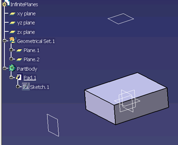
- Infinite planes
They are supported by AP214, AP214 edition3, AP203 edition2 and AP 242.
The name of the infinite plane in the specification tree is exported as
the name of the infinite plane in STEP (i.e. PLANE.NAME).
The visibility of the plane is taken into account like for the other
geometrical elements (according to the Show option).
|
|
|
The three default planes of a CATPart (xy
plane, yz plane and zx plane in the example below) are not taken into
account in the STEP export (only Plane.1 and Plane.2 are exported in the
example below).
 |
|
|
- Units:
The units used are V5 units i.e. MKSA
(radians, mm). The angles are exported in radians and lengths in mm or
Inch.
However:
AP242 XML .stpx or .stpxZ files do not support the
export to inch. If you have set the export unit to inch:
- The unit of the geometry (.step files) is inch.
- The unit of the assembly (.stpx files) is mm. AVP and instance
position transformations are affected.
- A warning is written in the .err file.
- Wires:
If a feature contains several wires (result of a section), the wires will
be exported as Composite Curves and will all have the same name (that of
the feature).
- Show/NoShow:
By default, hidden objects (i.e. that belong to the No Show space) are not
exported. See option
Show/NoShow.
- Selection set (AP214, AP214 edition3, AP242 only!):
For each selection set,an entity
APPLIED_GROUP_ASSIGNMENT is created. This entity points to a GROUP entity
and to a list of exported geometric entities. The attribute NAME of the
entity GROUP is defined by the name of the selection set.
The transfer of groups can be activated/de-activated via the
Groups (Selection Sets) option.
Note that selection sets are
not supported on V5 tessellated geometry.
|
|
- When a Body is contained in a Selection Set:
- a GROUP entity is created in the STEP file for that Selection Set,
- all the entities of the Body exported in STEP are put into that
GROUP.
- When an exported entity is contained in a Selection Set:
- a GROUP entity is created in the STEP file for that Selection Set,
- the entity is put into that GROUP.
- A solid resulting from a PartBody is exported in a group if and only
if the PartBody is in the Selection Set corresponding to the group.
If a feature of a PartBody is in a Selection Set, it is not taken into
account during export.
|
|
Annotations
See
About 3D Annotations in Graphic Mode and
About 3D Annotations in Authorable and Graphic Mode. Assemblies
Support of External References to STEP or V5 files
on Export: the External References functionality is available only with
AP214, AP214 edition3, AP203 edition2, AP242. For more information about the Customizing export mode,
refer to
Customizing STEP Settings.
- Multiple Instances of a Part in an Assembly is possible: a link with
the same reference is established in order to limit the number of
instances.
- STEP limitation with assemblies: since attributes can not be set on
instances of components, the color of instances are not taken into
account.
You can save the structure of an assembly with links to CATParts files
via PRODUCT_DEFINITION_WITH_ASSOCIATED_DOCUMENT entities.
.model files referenced by a CATProduct are exported in STEP with the
following settings:
- Application Protocol AP203 + Structure and Geometry in one file
- Application Protocol AP214 (or AP214 edition3, or AP242) + Structure and Geometry in one file
- Application Protocol AP214 (or AP214 edition3, or AP242) + STEP external references
- Application Protocol AP203 edition2 (or AP242) + STEP external references.
|
|
|
Only the active representation (not the alternative ones)
is exported. |
|
|
Light assemblies: The light geometry that can be
created with the workbenches Piping Design and HVAC Design is taken into
account while exporting to STEP.
The CATProduct designed by these workbenches contain applicative data having
a geometric representation that is not included in the geometric container
of a CATPart. This geometric representation is exported as STEP geometry.
The attributes of products
are taken into account as follows:
| V5 |
|
STEP |
| Part Number |
|
PRODUCT.ID |
| Definition |
|
PRODUCT.DEFINITION.ID |
| Nomenclature |
|
PRODUCT.NAME |
| Description |
|
PRODUCT.DESCRIPTION |
| Source |
|
PRODUCT_DEFINITION_FORMATION_WITH_SPECIFIED_SOURCE.MAKE_OR_BUY |
| Revision |
|
PRODUCT_DEFINITION_FORMATION.ID |
The attributes of instances of products are taken into account as
follows:
| V5 |
|
STEP |
| Component/Instance name |
|
NEXT_ASSEMBLY_USAGE_OCCURRENCE.ID |
| Component/Description |
|
NEXT_ASSEMBLY_USAGE_OCCURRENCE.DESCRIPTION |
|
|
|
In the Knowledge Base
STEP export of a product containing a part created by Visual Symmetry
STEP data exchange interface: Result of exporting/importing one single
feature containing several detached solids |
| |
|
Wire (GSM, Free Style,
etc.) |
Not generated by V5 |
OpenShell (GSM,
Shape Design, Free Style, etc.) |
Not generated by
V5 |
Geometrical set |
| |
Shape
Representation |
geometrically bounded
wireframe |
geometrically bounded surface |
edge-based wireframe |
shell-based wireframe |
manifold surface |
faceted brep |
advanced brep |
| |
High Level
Entities |
geometric_curve_set |
geometric_set |
edge_based_
wireframe_model |
shell_based_
wireframe_model |
shell_based_
surface_model |
faceted_brep
brep_with_voids |
manifold_solid_brep
brep_with_voids |
| |
Entity |
|
| |
Point |
cartesian_point |
Not V5 |
I |
Not V5 |
Not V5 |
I |
Not V5 |
I |
|
point_on_curve |
Not V5 |
Not V5 |
Not V5 |
N/A |
Not V5 |
N/A |
N/A |
|
point_on_surface |
N/A |
Not V5 |
N/A |
N/A |
Not V5 |
N/A |
N/A |
|
point_replica |
Not V5 |
Not V5 |
Not V5 |
N/A |
N/A |
N/A |
N/A |
|
degenerate_pcurve |
N/A |
Not V5 |
N/A |
N/A |
Not V5 |
N/A |
N/A |
| |
|
| |
Curve |
line |
Not V5 |
I |
Not V5 |
thru edge_curve |
I |
N/A |
I |
| |
circle |
Not V5 |
I |
Not V5 |
thru edge_curve |
I |
N/A |
I |
| |
ellipse |
Not V5 |
I |
Not V5 |
thru edge_curve |
I |
N/A |
I |
| |
hyperbola |
Not V5 |
Not V5 |
Not V5 |
thru edge_curve |
I |
N/A |
Not V5 |
| |
parabola |
Not V5 |
Not V5 |
Not V5 |
thru edge_curve |
I |
N/A |
Not V5 |
| |
polyline |
Not V5 |
Not V5 |
Not V5 |
Not V5 |
Not V5 |
N/A |
Not V5 |
| |
b_spline_curve
(+ rational)
b_spline_curve_with_knots |
Not V5 |
I |
Not V5 |
thru edge_curve |
I |
N/A |
I |
| |
uniform_curve (+rational) |
Not V5 |
Not V5 |
Not V5 |
Not V5 |
Not V5 |
N/A |
Not V5 |
| |
quasi_uniform_curve
(+rational) |
Not V5 |
Not V5 |
Not V5 |
Not V5 |
Not V5 |
N/A |
Not V5 |
| |
bezier_curve |
Not V5 |
Not V5 |
Not V5 |
Not V5 |
Not V5 |
N/A |
Not V5 |
| |
trimmed_curve |
Not V5 |
I |
N/A |
N/A |
N/A |
N/A |
N/A |
| |
composite_curve |
Not V5 |
I |
N/A |
N/A |
N/A |
N/A |
N/A |
| |
composite_curve_on_surface |
Not V5 |
Not V5 |
N/A |
N/A |
N/A |
N/A |
N/A |
| |
boundary_curve
outer_boundary_curve |
Not V5 |
Not V5 |
N/A |
N/A |
N/A |
N/A |
N/A |
| |
pcurve |
Not V5 |
Not V5 |
N/A |
N/A |
NI |
N/A |
NI |
| |
surface_curve |
Not V5 |
Not V5 |
N/A |
N/A |
NI |
N/A |
N/A |
| |
offset_curve_3D |
Not V5 |
Not V5 |
Not V5 |
Not V5 |
Not V5 |
N/A |
N/A |
| |
curve_replica |
Not V5 |
Not V5 |
Not V5 |
Not V5 |
Not V5 |
N/A |
N/A |
| |
|
| |
Surface |
plane |
N/A |
Not V5 |
N/A |
N/A |
I |
Not V5 |
I |
|
cylindrical_surface |
N/A |
Not V5 |
N/A |
N/A |
I |
Not V5 |
I |
|
conical_surface |
N/A |
Not V5 |
N/A |
N/A |
I |
N/A |
I |
|
spherical_surface |
N/A |
Not V5 |
N/A |
N/A |
I |
N/A |
I |
|
toroidal_surface |
N/A |
Not V5 |
N/A |
N/A |
I |
N/A |
I |
|
degenerate_toroidal_surface |
N/A |
Not V5 |
N/A |
N/A |
Not V5 |
N/A |
Not V5 |
|
surface_of_linear_extrusion |
N/A |
Not V5 |
N/A |
N/A |
I |
N/A |
I |
|
surface_of_revolution |
N/A |
Not V5 |
N/A |
N/A |
I |
N/A |
I |
|
b_spline_surface
b_spline_surface_with_knots |
N/A |
Not V5 |
N/A |
N/A |
I |
N/A |
I |
|
uniform_surface |
N/A |
Not V5 |
N/A |
N/A |
Not V5 |
N/A |
Not V5 |
|
quasi_uniform_surface |
N/A |
Not V5 |
N/A |
N/A |
Not V5 |
N/A |
Not V5 |
|
bezier_surface |
N/A |
Not V5 |
N/A |
N/A |
Not V5 |
N/A |
Not V5 |
|
rectangular_trimmed_surface |
N/A |
Not V5 |
N/A |
N/A |
N/A |
N/A |
N/A |
|
curve_bounded_surface |
N/A |
Not V5 |
N/A |
N/A |
N/A |
N/A |
N/A |
|
rectangular_composite_surface |
N/A |
Not V5 |
N/A |
N/A |
N/A |
N/A |
N/A |
|
offset_surface |
N/A |
Not V5 |
N/A |
N/A |
I |
N/A |
N/A |
|
surface_replica |
N/A |
Not V5 |
N/A |
N/A |
Not V5 |
N/A |
N/A |
| |
|
| |
Topology |
vertex_point |
N/A |
N/A |
Not V5 |
thru edge_curve |
I |
N/A |
I |
|
edge_curve |
N/A |
N/A |
Not V5 |
thru oriented_edge |
I |
N/A |
I |
|
oriented_edge |
N/A |
N/A |
N/A |
thru edge_loop |
I |
N/A |
I |
|
vertex_loop |
N/A |
N/A |
N/A |
Not V5 |
Not V5 |
N/A |
Not V5 |
|
poly_loop |
N/A |
N/A |
N/A |
Not V5 |
N/A |
Not V5 |
N/A |
|
edge_loop |
N/A |
N/A |
N/A |
thru wire_shell |
I |
N/A |
I |
|
face_bound
face_outer_bound |
N/A |
N/A |
N/A |
N/A |
I |
Not V5 |
I |
|
face_surface |
N/A |
N/A |
N/A |
N/A |
Not V5 |
Not V5 |
N/A |
|
advanced_face |
N/A |
N/A |
N/A |
N/A |
I |
Not V5 |
I |
|
oriented_face |
N/A |
N/A |
N/A |
N/A |
Not V5 |
N/A |
N/A |
|
vertex_shell |
N/A |
N/A |
N/A |
Not V5 |
N/A |
N/A |
N/A |
|
wire_shell |
N/A |
N/A |
N/A |
Not V5 |
N/A |
N/A |
N/A |
|
connected_edge_set |
N/A |
N/A |
Not V5 |
N/A |
N/A |
N/A |
N/A |
|
open_shell |
N/A |
N/A |
N/A |
N/A |
I |
N/A |
N/A |
|
oriented_open_shell |
N/A |
N/A |
N/A |
N/A |
N/A |
N/A |
N/A |
|
closed_shell |
N/A |
N/A |
N/A |
N/A |
I |
Not V5 |
I |
|
oriented_closed_shell |
N/A |
N/A |
N/A |
N/A |
N/A |
Not V5 |
I |