- General STEP options:
- Import STEP options:
- Export STEP options:
The values impacted will be displayed with the unit of the V5 session.
The range values will take into account the scale factor of the session.
- When you modify the scale within a session, the values impacted
are not automatically re-computed. Either:
- key-in the new values according to the messages displayed,
- or click Default Values to update the parameters or tolerances according to the new scale,
- or delete obsolete STEP settings files.
- The tolerance used in Automatic optimization takes the scale into account.
General
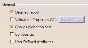
Detailed report
By default, the report file contains a Detailed Conversion chapter. Click to clear the Detailed Report option to remove this chapter from the report file.
Validation Properties (VP)
Read the section About Validation Properties for more information on the Validation Properties mechanism.
Once you have activated this option, Validation Properties (VP)
become active and Parameters becomes available. It starts
the Parameters for Validation Properties dialog box:
-
If you switch to another scale, the current value
may become invalid.
When this happens, a warning message is issued and you are invited to define new values:For Small Scale: - for the centre of gravity, between 0.0001 and 0.05mm
- for the SAG for COPS, between 0.0001 and 0.01 mm
- for the COPS deviation, between 1e-005mm and 0.001mm
For Large Scale:
- for the centre of gravity, between 1 and 500 mm
- for the SAG for COPS, between 1 and 1000 mm
- for the COPS deviation, between 0.1 and 10mm
In this dialog box, you can:
- activate Geometric Validation Properties (GVP) or Assembly Validation Properties (AVP) according to your needs (explained in About Validation Properties).
- activate the Clouds of points (COPS) functionality (This functionality involves a slight performance loss, due to the properties computation cost.)
- define the tolerances for the validation properties checking.
Tolerances for Geometric Validation Properties checking detect large errors during exchanges by comparing the centre of gravity, the volume and the area of the exchanged solids with their native properties:
- Volume and area max. Deviation is a percentage of variation of volume or area allowed. Default value: 1%.
- Centre of gravity max. Deviation is the maximum error for the center of gravity. Default value: 1mm for the Standard Scale, 0.01mm for the Small Scale and 100 mm for the Large Scale.
SAG for COPS creation density controls the density of the cloud of points generated for each face; the cloud of point is created by tessellating the face according to the given SAG: a low value of SAG means a large number of points by face and a high value of SAG means few points by face. The SAG must be defined between 0.01 and 10. The default value is 0.1 mm.
Tolerance for COPS deviation is the largest allowed gap between a point and the imported face. With a standard scale, the deviation must be defined between the following bounds 0.0001 and 0.1. The default value is 0.01 mm.
Default Values reverts to the default values.
![]() By default,
By default,
- the option Validation Properties (VP) is not selected.
- In the Parameters dialog box:
- Volume and area max. Deviation is 1,
- Centre of gravity max. Deviation is 1 mm
- the option Cloud of points (COPS) is not selected.
- SAG for COPS creation density is 0.1 mm.
- Tolerance for COPS deviation is 0.01 mm.
- the option Geometric Validation Properties (GVP) is selected.
- the option Assembly Validation Properties (AVP) is not selected.
- The unit used for geometric validation properties is the STEP length user unit. See Unit option.
- This functionality involves a slight performance loss, due to the properties computation cost.
Groups (Selection Sets)
By default, this option is selected:
- at import, Groups found in the STEP file are translated into Selection Sets.
- at export, Selection Sets found in the V5 file are exported as Groups in the STEP file. Refer to the STEP: Export chapter for more information (Miscellaneous section).
However, importing or exporting Groups may be time consuming. Click to clear this option and de-activate the processing of Groups.
Composites
When selected, this option enables the import and export of Composites data.The import and export of Composites data are supported by AP203 ed2/AP242.
User Defined Attributes
When selected, this option enables the import and export of
user parameters as STEP User Defined Attributes (UDA).
The import and export of User Defined Attributes are supported by
AP214/AP214 ed3/AP203 ed2/AP242.
Import
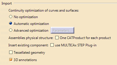
Continuity optimization of curves and surfaces
This setting allows a better user control over the number of
curves and surfaces that are created during the process of importing STEP
data into V5:
V5 requires its geometry to be C2-continuous. When non C2-continuous
geometry must be imported from a STEP file, this geometry (curves, surfaces)
is broken down into a set of contiguous geometries, each of them being
C2-continuous. This is what happens when the No Optimization option is
chosen.
However, this can produce an increase of the size of the resulting data,
because more curves/surfaces are created. In order to limit this drawback,
two other modes are optionally offered.
In those modes, the STEP interface tries to limit the splitting of curves
and surfaces by modifying their shape slightly, so that they become
C2-continuous while remaining very close to their original shape.
In order to guarantee that the deformation is not excessive, a maximum
deviation parameter is used. When in Automatic optimization
mode, this maximum deviation is read into the STEP file itself, in the STEP
parameter that documents the precision of points in the file. In this mode,
the value read from the STEP file is then corrected so that it remains
comprised between 0.005 and 10E-3. This guarantees an optimization that
remains compatible with the precision for the data that was set by the
emitting system.
Last, if this strategy is not enough, you can choose the Advanced
optimization mode, in which an arbitrary deviation value can be
entered.
You can find useful information in the report file. Please see the Report file section in the STEP Import chapter in this User's Guide.
The Automatic optimization proposes:
- No approximation, thus this option does not create a significant deformation and keeps the internal BSpline structure (equations and knots).
- A continuity optimization is performed within the deformation tolerance used for optimizing BSplines, comprised between 0.001mm and 0.01mm (depending on the tolerance value defined within the imported STEP file) on:
- BSpline surfaces,
- BSpline boundary curves (3D and P-curves when available),
- BSpline independent 3D curves,
- The parameters box cannot be activated
This option softens the effect C2 cutting of faces and boundaries (which is mandatory in V5) without any significant geometric deformation.
If you select No optimization:
- No optimization is performed on BSplines (neither curves nor surfaces).
- Elements are cut at discontinuity points to suit the modeler (exact mathematic continuity). This may result in a dramatic number of faces and boundary curves, data of poor quality and poor performances in further use in V5.
If you select Advanced optimization:
- No approximation. The internal BSpline structure (equations and knots) is kept,
- A continuity optimization is performed on:
- BSpline surfaces,
- BSpline boundary curves (3D and P-curves when available),
- BSpline independent 3D curves,
- but the deformation tolerance is set by the user (see Parameters).
With this option, you can enter a larger tolerance value which may enhance the optimization impact (resulting in less C2 cutting on faces).
Click Parameters to
access advanced optimization options and tolerances.
The dialog box looks like this if you have selected Standard Scale:
The default value is:
- 0.3 mm for Large Scale,
- 0.003mm for Standard Scale,
-
3e-005 mm for Small Scale.
Note that the tolerance is shared by the optimization
process (in all cases), the Curves and surfaces approximation and the
Topological reduction of boundaries if you have selected those check boxes.
For example, you have a deformation tolerance of 0.001mm and
you have selected Curves and surfaces approximation.
The tolerance for the optimization will be 50%, i.e. 0.0005mm and that of
the Curves and surfaces approximation will also be 50%.
Thus, the number of cuts of the faces will vary according to
the value entered, and according to the number of check boxes selected.
-
Deformation: maximum deformation (in millimeter) allowed
in the optimization of curves and surfaces:
- For the Standard Scale, it ranges between 0.0005 and 0.1mm. The default deformation is 0.003mm.
- For the Small Scale, it ranges between 5e-006mm and 0.001mm. The default deformation is 3e-005mm.
- For the Large Scale, it ranges between 0.05mm and 10mm. The default deformation is 0.3mm.
Click Default Value to revert to the default value.
User-defined Advanced Option: Curves and surfaces approximation:
- By default, this option is not selected.
- BSpline surfaces and curves continuity is optimized,
- In addition, Bspline curves and surfaces approximation is performed,
- It is possible to enter a user value for Deformation,
- This option may change the internal structure of BSplines (equations and knots),
- This option usually results in a significant decrease in the number of faces cuttings.
Assemblies physical structure
This option enables the processing of sub-assemblies of an imported assembly.
A CATProduct file containing the whole
assembly structure and a CATPart file for each part of the assembly are
created.
If you select this option, a CATProduct file containing the sub-assembly
structure is created for each node of the whole assembly while a CATPart
file is created for each part of the whole assembly.
| STEP File | One CATProduct for each product
is not selected |
One CATProduct for each product
is selected |
| Assembly file containing the geometry of components
|
1 CATProduct + N CATPart
|
P CATProduct + N CATPart
|
| Assembly file referencing STEP files containing the geometry of components
|
1 CATProduct + N CATPart
|
P CATProduct + N CATPart
|
| Assembly file referencing native files containing the geometry of components
|
1 CATProduct + N native files
|
P CATProduct + N native files
|
Insert existing component
This option appears only if both the V5 - STEP Interface (AP214/AP214 ed3/AP203 ed2/AP242) and the MULTICAx STEP Plug-in exist on
the machine.
Select this option to insert the component using the
MULTICAX STEP Plug-in instead of STEP Interface.
Before inserting the
component, select the appropriate options in Tools > Options >
Compatibility > External Formats.
Tessellated geometry
Requires AP242 ed1.
When both a tessellated and an exact representation exists in a STEP file, and when Tessellated geometry is selected, the tessellated representation is imported.
3D annotations
When selected, this option enables the import of 3D annotations. They are automatically processed in graphic or semantic mode.See About 3D Annotations in STEP and About 3D Annotations in Authorable and Graphic Mode.
Export
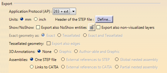
Application Protocol (AP)
The data contained in a CATPart or CATProduct document will
be saved in STEP AP214/AP214 ed3/AP203 ed2/AP242 formats.
For more information about the Application Protocols, refer to STEP:Export.
 Exact
geometry as
Exact
geometry as
Requires AP242 ed1.
Select the option corresponding to your needs:
- Exact to force the export as exact geometry,
- Tessellated to force the export as tessellated geometry,
- Exact and Tessellated to keep both formats.
Tessellated
geometry
Export also edges applies to the tessellated geometry
created in the STEP file, either because it was present in the content to
export, or because Tessellated or Exact and Tessellated
is selected (see above).
When this option is cleared, exported
tessellated solids and surfaces only contain faces, thus reducing the size
of the STEP file.
When this option is selected, exported tessellated
solids and faces contain faces and edges.
When 3D annotations are
exported, solid and shells are always exported with their edges to keep the
links between annotations and edges.
Units
![]()
Show/NoShow
![]()
By default, those options are not active.
A CATPart to export may contain:
- visible entities placed in the Show space,
- hidden entities placed in the NoShow space. By default, they are not exported.
-
hidden entities placed in layers that are not visualized
(for more information, see
Using Visualization Filters).
Visualization filters are now taken into account: by default, entities placed in non-visualized layers are no longer exported.
Select the Export also NoShow entities option to
export all entities belonging to both the "Show" and the "NoShow" spaces.
Select the Export non-visualized layers option to
export also all entities belonging to those layers.
STEP export manages invisibility in assemblies as follows:
- invisible instances of a product or a component are not exported,
- an instance is considered as invisible for export in a given product or component if it is invisible in all instances of this given product or component.
For example:
Let's consider the instances of AAA in the products above:
- AAA is considered as visible for export in Product10, because it is visible in at least on instance of Product10.
- AAA is considered as invisible for export in Product9 as it is invisible in all instances of Product9.
- AAA is visible in both instances of Product10, as AAA was considered as visible for export in the initial Product10.
- There is no instance of AAA in Product9 as AAA was invisible in that product.
Header of the STEP file
![]()
Click Define... to
define the header of the STEP file:
Fill in the form displayed as required. Click Default
Values to revert to the Default Values of the header.
The header of the exported file looks like this:
3D Annotations

Select the required option to prevent or enable export of 3D Annotations.
- None: 3D annotations are not exported.
- Graphic: 3D annotations are exported as STEP PMI Graphic Presentation entities.
- Authorable and Graphic: 3D annotations are exported as STEP AP242 PMI Semantic Representation entities and as STEP AP242 PMI Graphic Presentation entities, linked by STEP draughting_model_item_association entities (DMIA).
See About 3D Annotations in STEP and About 3D Annotations in Authorable and Graphic Mode.
Assemblies
- One STEP file and Links to CATIA are available for all Application Protocols while External references to STEP, Global nested assembly and Partial nested assembly are available for AP214/AP214 ed3/AP203 ed2/AP242 as stated in Recommended Practices for External References, Release 2.1, dated January 2005.
- If you have no STEP license, a CATProduct can be exported only in Links to CATIA mode.
- One STEP file creates one STEP file only, that contains the
structure and geometry of the components.
This option does not support AP 242 XML format. - Links to CATIA creates one STEP file that contains the structure and entities PRODUCT_DEFINITION_WITH_ASSOCIATED_DOCUMENT which have a link with CATPart files.
- External references to STEP creates:
- one STEP file containing the structure
- and a STEP file for each component. The STEP file names, for each component, have the same name as the components. The structure and the component STEP files are generated in one shot, in the same location.
- A STEP file cannot refer to a STEP assembly file.
- External
references to CATIA: one STEP file containing the assembly
structure with external links to CATPart, CATShape, model V4, .cgr, .wrl
files, according to AP214/AP214 ed3/AP203 ed2/AP242 external references
mechanism.
Note: If you have no STEP license, a CATProduct can be exported only in Links to CATIA mode. - Global nested assembly creates a set of STEP
files:
- one assembly STEP file for each product that has children,
- one part STEP file for each product containing representations.
Two STEP files are created for each product that has both children and representations.
- The root STEP file takes the name you provide. The other assembly STEP files have the name of their product. The part STEP files have the name of their product with a suffix _rep.
- Each assembly STEP file contains external references to the STEP files corresponding to their children.
- Partial nested assembly is similar to Global nested assembly but takes only the root product into account. It creates one assembly STEP file and/or one part STEP file.
- Export to STEP XML files requires AP242 ed1.
- When an External references option is
selected, the assembly structure is represented
by one STEP XML file which references geometry files.
The referenced geometry files can be STEP files (External references to STEP) or CATIA native files (External references to CATIA or Links to CATIA that are strictly equivalent). - When a Nested option is selected, the assembly structure is represented by several STEP XML files: one stpx file by CATProduct file. Two files are created for one part: One STEP XML file and one STEP file.
- To export in nested assembly, choose the option Global
nested assembly that exports the whole assembly whereas Partial nested assembly only the file corresponding to the selected product.
- If several products of an assembly have the
same name, the duplicated products are not exported.
Error messages are written in the .err and .rpt files.
- You are responsible for the consistency of the set of STEP files generated. While Global nested assembly creates a consistent set of STEP files, it is your responsibility to update this set of files when using the Partial nested assembly option.
- We recommend that you name the exported STEP files with the name of the exported product.
- To avoid naming inconsistency, when the options Global nested assembly or Partial nested assembly are selected, the visibility status of instances in the assembly are not taken into account: the instances are exported as visible whatever their visibility status.
- The flexibility of assemblies as described in the section STEP export is not taken into account.
- If Geometric Validation Properties (GVP) is selected, the assembly STEP files do not contain geometric validation properties.
- If Assembly Validation Properties (AVP) is selected, the assembly STEP files contain the assembly validation properties.