Following validation properties are available:
- Geometric Validation Properties for 3D Exact Geometry
- Geometric
Validation Properties for Tessellated Geometry
- Annotation Validation
Properties for 3D Tolerancing & Annotation
-
Validation Properties for User
Defined Attributes
- Validation Properties for Composites
- Assembly Validation Properties
General Information
For each type of data, validation properties are specified through the recommended practices.
The following validation properties are available:
- Geometric Validation Properties (GVP) for geometric exchange (at part and assembly level)
- Assembly Validation Properties (AVP) for assembly structure exchange (at assembly level)
- Annotation validation properties for 3D Tolerancing & Annotation exchange (at part level)
- Validation Properties for User Defined Attributes
- Validation Properties for Composites.
For AP 242 XML files, GVP are used for geometry (.stp or .stpZ files) and not for assembly (.stpx or .stpxZ). Assembly .stpx or .stpxZ files support only AVP.
Validation properties are:
- Computed on the native data at export and are stored in the STEP file,
- Computed on the imported data at import and compared with the validation properties found in the STEP file. A status of comparison is provided in the report file.
Validation Properties (VP) can be activated in Tools > Options > STEP, under General. Parameters becomes available to let you select the options and set the parameters in the Parameters for Validation Properties dialog box.
- Under Assemblies:
- Geometric Validation Properties (GVP)
GVP are not supported by STEP XML files. - Or Assembly Validation Properties (AVP) (recommended for assemblies, supported by STEP XML files) according to your needs.
- Geometric Validation Properties (GVP)
Geometric Validation Properties for 3D Exact Geometry
Geometric Validation Properties can be used at several levels.
- Geometric Validation Properties are defined independently for each class of geometry (solids/surfaces/curves), for each part, each assembly node and each geometric element.
- Geometric Validation Properties for curves are supported at assembly level.
- Geometric Validation Properties for bounding box are supported at part level.
Validation Properties of Elements of a Part At Export
The STEP file includes geometric validation properties for
- Each solid
- Centroid: Coordinates of the center of gravity
- Area: Area of the entity (wetted area for solids)
- Volume: Volume of the entity
- Each shell or surface
- Centroid: Coordinates of the center of gravity
- Area: Area of the entity
- Each contour or curve
- Centroid: Coordinates of the center of gravity
- Length: Length of the entity (applied to contour).
- The bounding box of the part
- It is defined by two points
and a diagonal in space.
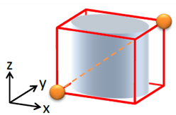
- Only the visible 3D elements
of the geometry are taken into account.
Annotations and axis systems are not taken into account. - The edges of the bounding box are parallel to the axes of the part coordinate system.
- It is defined by two points
and a diagonal in space.
These properties are completed in the export report with the estimation of their computation errors for each solid and each shell at export and at import.
- The estimation of the computation error on the area or the volume is provided as a relative value.
- The estimation of the computation error on the centre of gravity is provided as an absolute value for each coordinate and a bounding box of the entity.
Validation Properties of Elements of a Part At Import
For each imported solid, shell, surface, contour or curve and for the imported part as a whole, the report file indicates the geometric validation properties computed on the imported data, the GVP read in the STEP file and the status of comparison between the two sets of GVP.
In addition, the report at import provides the GVP status and the following error information computed on each imported solid or shell.
- In most cases, the centroid deviation error that applies to solid, shell, product or instance, is given as a percentage based on the bounding box. However, when the deviation error is under a threshold, it is given as a distance.
- The surface area difference value and error ratio apply to solid, shell or product.
- Volume difference value and error ratio apply to solid or product.
- The bounding box appears with the two points and the diagonal in space shown above.
These properties are completed with the estimation of their computation errors for each solid and each shell.
- The estimation of the computation error on the area or the volume is provided as a relative value.
- The estimation of the computation error on the centre of gravity is provided as an absolute value for each coordinate and a bounding box of the entity.
Clouds of Points (COPS)
When standard validation properties are not accurate enough, e.g. for aeronautic long term archiving, COPS ensure that the archived data are equivalent to the native data, within a given tolerance by comparing any face with any check point lying on it.
- At export:
- The STEP file is enriched with COPS properties (i.e. a cloud of points) for each exported face.
- These points are computed inside the face, on the support of the face, or on the boundary of the face.
- The syntax of the STEP file respects the Recommended Practices.
- At import:
- For each face, the COPS properties are read and the distance between each point of the cloud and the support surface of the face is computed.
- If the distance is greater than a user defined tolerance, there is an error message in the err file.
Note:
- The check at import is reported only in the report and error files.
- The repartition of the points in the face is automatic. A high curvature generates many points.
- You cannot define an area to be controlled by COPS. The whole product exported is checked.
- The unit used for geometric validation properties is the STEP length user unit.
Validation Properties of a Part
The exported STEP file includes geometric validation properties for a Part :
- Centroid: Coordinates of the center of gravity (applies to solid, shell and contour)
- Area: Area of the entity (wetted area for solids) (applies to solid and shell)
- Volume: Volume of the entity (applies to solid)
- Length: Length of the entity (applied to contour)
Validation Properties of an Assembly
When the option is selected the exported STEP file includes geometric validation properties for Products and intances :
- Centroid: Coordinates of the center of gravity (applies to product and instances)
- Area: Area of the entity (wetted area for solids) (applies to product)
- Volume: Volume of the entity (applies to product).
Validation Criteria
The status of comparison for a given solid or shell or contour is ok if:
- Ratios (Volume difference and Surface area difference and Length difference) are lower than the user tolerance.
- And the centroid deviation is lower than the user tolerance, or the ratio (centroid deviation versus entity size) is lower than the user tolerance.
Geometric Validation Properties for 3D Tessellated Geometry
Geometric Validation Properties can be used at several levels. The check for area and centroid is performed according to fixed tolerances.
Validation Properties of Elements of a Part
Available validation properties are:
- For solid, shell or surface set
- Number of facets,
- Surface area,
- Centroid
- For wire or curve set
- Number of segments
- Total length
- Centroid
- For point set:
- Centroid
Validation Properties of a Part
Available validation properties are:
- Number of facets
- Surface area
- Number of segments
- Total length of all contours of the part
- Centroid of the part
- Bounding box (defined by two opposite points).
The centroid represents the centroid of facets if there are solids, shells or surface sets. Otherwise it represents the centroid of wire or curve, if any, otherwise it represents the centroid of point sets.
Validation Criteria
They are:
- The maximum percentage of variation for volume, area, length for solids, shells, contours and variation for centroid deviation versus model size
- The maximum variation for centroid.
Note: For a centroid, a deviation higher than the maximum variation is valid if the percentage of variation for the centroid deviation versus the model size is lower than the maximum percentage.
Examples
Below are some extracts of import report files.
- Curve
#176 Circle.2 Type: COMPOSITE_CURVE Transferred correctly
Computed Properties: Length:3.544908e+mm - wire centroid:(0.000000 mm,10.000000 mm,0.000000 mm)
Read Properties : Length:3.744908e+mm - wire centroid:(0.000000 mm,10.000000 mm,0.000000 mm)
Validation failed : Error ratio: Length:5.641896% - wire centroid:0.000000% / 0.000000mm - - Solid
#2614 PartBody Type: MANIFOLD_SOLID_BREP transferred correctly
Computed Properties: Area:1.840000e+004 mm2 - Volume:1.200000e+005 mm3 - Centroid:(-130.000000 mm,70.000000mm,10.000000 mm) - Area:Relative Error:0.000% - Volume:Relative Error:0.000%
Centroid:Absolute Errors:(0.000 mm,0.000 mm,0.000 mm) - Box sizes:(100.0 mm,60.0 mm,20.0 mm)
Read properties: Area:1.840000e+004 mm2 - Volume:1.200000e+005 mm3 - Centroid:(-130.000000 mm,70;000000 mm,10.000000 mm) -
Validation successful: Error Ratio: Area:0.000000% - Volume:0.000000% - Centroid: 0.000000% / 0.000000mm - Surface with AP242 ed1
#335 Surface.1 Type: OPEN_SHELL Transferred correctly
Computed properties: Shell Area:3.698668e+004mm2 - Shell Centroid:(-64.086136 mm,1.631528 mm,6.504039 mm) - Relative error:0.000% Centroid: Absolute Errors:(0.000 mm,0.000 mm,0.000 mm) - Box sizes:(125.4 mm,260.2 mm,41.2 mm)
Read Properties: Shell Area:3.698668e+004 mm2 - Shell Centroid:(-64.086021 mm,1.631612 mm,6.504087 mm) -
Validation succesful: Error ratio: Shell Area:0.000227% - Shell Centroid:0.000052% / 0.000150mm - - Surface with AP 214
#197 Fill.1 Type:OPEN8SHELL Transferred correctly
Computed Properties: Area:1.000000e+002 mm2 - Centroid:(0.000000 mm,10.000000 mm,0.000000 mm) - Area:Relative error:0.000% Centroid:Absolute Error:(0.000 mm,0.000 mm,0.000 mm)- Box sizes:(0.0 mm,11.3 mm,11.1 mm)
Read Properties: Area:1.000000e+002 mm2 - Centroid:(0.000000 mm,10.000000 mm,0.000000 mm) -
Validation successful : Error Ratio: Area:0.000000% - Centroid: 0.000000% / 0.000000mm - Part
Geometric Validation Properties at Part level:
Computed Properties: Area:1.840000e+004 mm2 - Shell Area:3.698676e+004 mm2 - Volume:1.200000e+005 mm3 - Length:2.049061e+003 mm - Centroid:(-130.000000 mm,70.000000 mm,10.000000 mm) - Shell Centroid:(-64.086136 mm,1.631528 mm, 6.540039 mm) - Wire Centroid:(12.11368 mm,58.306047 mm,-2.138570 mm) Bounding Box: Corner Points:(-180.00 mm,-132.36 mm,-66.35 mm)(107.23 mm,241.84 mm,87.94 mm) - Diagonal: 496.315883 mm
Read Properties: Area:1.840000e+004 mm2 - Shell Area:3.698668e+004 mm2 - Volume:1.200000e=005 mm3 - Length:2.049.61e+003 mm - Centroid:(-130.000000 mm,70.000000 mm,10.000000 mm) - Shell Centroid:(-64.086136 mm,1.631528 mm, 6.540039 mm) - Wire Centroid:(12.11368 mm,58.306047 mm,-2.138570 mm) Bounding Box: Corner Points:(-180.00 mm,-132.36 mm,-66.35 mm)(107.23 mm,241.84 mm,87.94 mm) - Diagonal: 496.315883 mm
Validation successful: Error Ratio: Area:0.000000% - Shell Area:0.000227% - Volume:0.000000% - Length0.000000% - Centroid:0.000000%/ 0.000000mm - Shell Centroid:0.000030% / 0.000150mm - Wire Centroid:0.000000% / 0.000000mm - Bounding box:0.000000% - Instance
Assemblage Composition:

				Centroid:(-29.380994 mm,105.876987 mm,-111.474132 mm) - Centroid
				read:(-29.380994 mm,105.876987 mm,-1411.474132 mm)

Validation successful: Centroid Position Error:0.000000 mm - Assembly Product
#71 Composition1:
Computed Properties: Area:9.089815e+002 mm2 - Shell Area:1.000000e+002mm2 - Volume:2.000000e+003mm3 - Length:1.354491e+002 mm - Centroid:(50.000000 mm,-0.000000 mm,10.000000 mm) - Shell Centroid:(0.000000 mm,10.00000 mm,0.000000 mm) - Wire Centroid:(-0.000000 mm,2.617152 mm,22.343627 mm)
Read Properties: Area:9.089815e+002 mm2 - Shell Area:1.000000e+002mm2 - Volume:2.000000e+003mm3 - Length:1.354491e+002 mm - Centroid:(50.000000 mm,0.000000 mm,10.000000 mm) - Shell Centroid:(0.000000 mm,10.000000 mm,0.000000 mm) - Wire Centroid:(0.000000 mm,2.617152 mm,22.343627 mm)
Validation successful: Error Ration: Area:0.000000% - Shell Area:0.000000% - Volume:0.000000% - Length:0.000000% - Centroid Position Error:0.000000 mm - Centroid Shell Position Error: 0.000000 mm Centroid Wire Position error:0.000000 mm - - Maximum Errors
Geometric validation properties
				check: OK
Maximum errors:
Centroid: #2614: 0.000000 mm

Volume: #2614: 0.000000 %
Area: #2614: 0.000000 %

				Length: #242 : 0.000000 %
Shell centroid: #335: 0.000150 mm

Wire Centroid: #242: 0.000000 mm
Shell Area: #335:
				0.000227%
Annotation Validation Properties for 3D Tolerancing & Annotation
Annotations, also known as Product Manufacturing Information (PMI)
can be presented as polylines
![]()
or as tessellated
![]()
Validations properties apply to graphic annotations only.
Validation Properties of Elements of a Part
For the saved views (captures), they are:
- Number of annotations per saved view (capture)
For the polyline presentation, they are:
- Total length of the polylines representing each annotation
- Centroid of the polylines representing each annotation
- Affected geometry (AP 242 only).
For the tessellated presentation, they are:
- Total length of the lineic tessellations found in each annotation
- Centroid of the lineic tessellations found in each annotation
- Number of the lineic elements
- Total area of the surfacic tessellations found in each annotation
- Centroid of the surfacic tessellations found in each annotation
- Number of surfacic elements
- Affected geometry (AP 242 only).
Affected geometry contains:
- The area of the geometry linked to the PMI, if the geometry is a face (Affected area).
- The length of the geometry linked to the PMI, if the geometry is a curve (Affected curve length).
At import, the Affected Geometry properties are computed and compared with the values found in the STEP file. The computed error is given as a percentage in the report file. If this percentage exceeds 5%, the validation fails.
Export and import as both exact and tessellated are not supported.
Example
Computed Properties : Number of Facets:8 - Number of Segments:9 - Centroid:(-63.329167 mm,5.603107 mm,15.392448 mm) - Total area:4.221e+000 mm2 - Centroid of facets:(-89.998539 mm,5.603107 mm,10.004080 mm) - Total length:9.803e+001 mm – Affected area: 25.40000 mm2
Read Properties : Number of Facets:8 - Number of Segments:9 - Centroid:(-63.329168 mm,5.603107 mm,15.392448 mm) - Total area:4.221e+000 mm2 - Centroid of facets:(-89.998539 mm,5.603107 mm,10.004080 mm) - Total length:9.803e+001 mm - Affected area: 25.3900 mm2
Validation successful: Length Error:0.000000 mm - Area Error:0.000000 % - Number of segments Error:0 - Number of facets Error:0 - Centroid Position Error:0.000000 mm – Affected Area Error:0.040000 %
Validation Properties of a Part
They are:
- Number of annotations
- Number of saved views (captures).
Example of validation properties of a part:
<>Expected number of annotations: 48, found: 48

Expected number of captures: 0, found: 0

Annotation Validation Properties Check: OK
Validation Properties for User Defined Attributes
There are two types of validation properties for the User Defined Attributes.
Validation Properties of Elements
For elements, they are:
- The counts of User Defined Attributes for a given type of link, i.e. linked to a solid or a shell.
- The counts of User Defined
Attributes for a given type:
- Real or measure with unit
- Integer
- String
- Boolean.
- Count of User Defined Attributes linked to a contour.
- Count of User Defined Attributes linked to a point.
At export, when a count is null, the validation property is not exported in the STEP file. There are no trails of these validations properties in the report file.
At import, when a validation property is found in the STEP file or computed, a comparison status is provided in the report.
Composites Validation Properties
Composites Validation Properties can be used at several levels.
Validation Properties of Elements of a Part
They are:
- Count of sequences (applies to a laminate table)
- Count of plies (applies to a sequence)
- Count of core (applies to a sequence)
- Count of cut pieces (applies to a ply).
Validation Properties of a Part
They are:
- Count of laminate tables
- Count of sequences
- Count of plies
- Count of cores.
Assembly Validation Properties
Assembly Validation Properties can be used at several levels
For each product having instances, the number of instances and a notional centroid are stored in the STEP file as validation properties at export and checked at import.
- At export, for each product, 2 properties are stored in the STEP
file
- The number of instances
- The notional centroid (useful for checking the position of each instance of the product).
-
At import, the status for validation properties in the report file takes into account the validation properties check at assembly level, done according to the option.
- If product assembly properties are found, these properties are checked and Product/Instances geometric validation properties, if any, are ignored.
- When assembly properties are checked, the result of the comparison of the assembly properties appears in the report file for each product.