Under Tools > Options > Compatibility > STEP
- Set the 3D Annotations option to Graphic under Export export 3D Annotations in graphic mode,
- For import, select the 3D annotations option under Import.
The following topics are discussed:
3D Annotations pointing to CGR behave like 3D Annotations in 3D XML Files. This is explained in Managing 3D Annotation in 3D XML Files in DMU Tolerancing Review User's Guide.
Export
Annotations comply with some rules at export.
At export:
- With AP203 ed2 and AP214 ed3 3D annotations are exported to the STEP file as polyline PMI.
- With AP242 ed1 3D annotations are exported to the STEP file as tessellated PMI.
Each V5 FTA annotation is exported as an ANNOTATION_OCCURRENCE in STEP, with its type and its user name.
Each V5 view is exported as an ANNOTATION_PLANE, with the lists of the annotations it contains and the
V5 view name.
The type of view is not kept. Each annotation is related to one ANNOTATION_PLANE, and only one.
Each V5 capture is exported as a DRAUGHTING_MODEL with the list of annotations it contains,
its name and the capture camera (viewpoint):
- The capture is exported as a DRAUGHTING_MODEL which takes the user name of the capture and points to each annotation the capture contains.
- The viewpoint associated to the camera is exported as a
CAMERA_MODEL_D3 according to the Recommended Practices.
The 3D Tolerancing & Annotation features that are
in the NoShow are exported in STEP whatever the STEP Show/Noshow option is.
Import
When the 3D annotations
under Import is selected, PMI Graphic Presentation entities are imported
"as result" annotations belonging to a Result Annotation Set.
Import of PMI Semantic Representation entities is explained in
About 3D Annotations in Authorable and Graphic Mode.
- With AP203 ed2 and
AP214 ed3 3D annotations are
imported as polylines

- With AP242 ed1
annotations are imported as specified in the STEP file, either as
polylines
oras tessellated

- Are created with their original type and user name. However, due to mapping constraints, the type may be different as the original one in some cases.
- Can be filtered by type and capture.
- Can be highlighted together with the related geometrical entities.
The ANNOTATION_PLANE is used to create the views.
The DRAUGHTING_MODEL is used to create the capture.
Construction Geometry
Only the construction geometry at part level is taken into account.
The construction geometry is made of:

- Points (apex, centers…),
- Lines (axis),
- Planar faces,
- Cylindrical faces.
The construction geometry entities are exported like standard geometrical entities as follows:
- Point -> STEP Point,
- Line -> STEP Line,
- Planar face -> STEP Face,
- Cylindrical faces -> STEP Faces.
These STEP entities are organized in the STEP file according the STEP
Recommended Practices.
These entities are not taken into account in the
computation of the validation properties.
At import, the geometrical entities that are identified in the STEP file as construction geometry are imported as standard geometrical entities, regrouped into a dedicated additional geometrical set named Construction geometry:
- This geometrical set has a transparency attribute so that the geometrical entities looks like the native construction geometry (transparent by default).
- When you export this part again, the construction geometry found in the geometrical set is processed as standard geometry.
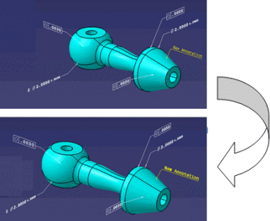
Re-export of Result Annotations after STEP Import
A CATPart resulting from a STEP import and containing result FTA annotations can be exported to STEP while taken into account the FTA annotations and their link to the geometry:
- first import:
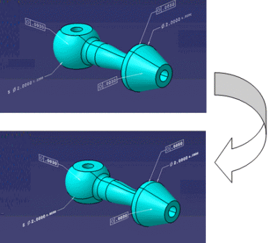
- import of the exported Result Annotations:
Modification of the CATPart resulting from STEP import by adding a new yellow annotation:
Limitations
In assemblies exchanges, only the annotations at Part level, inside a CATPart are taken into account:
- Annotations inside a V4 model are ignored,
- Annotations at CATProduct level are ignored.
The Annotation Set in the specification tree is not strictly preserved in
the STEP exchange.
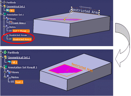
The FTA that are not related to a V5 view are not exported:
- Restricted Area (no visualization; its underlying geometry is
exported),
- Datum Reference Frame (no visualization),
- Distance, Maximum Deviation (not included in the Part definition).
The type/subtype of the FTA is not always preserved in the STEP exchange (the icon may change in the specification tree after import):
- The distinction between non semantic dimension and semantic dimension is not preserved.
- The distinction between non semantic datum and semantic datum is not preserved.
- Some specific tolerances such as a pattern location become general tolerance in STEP and NOA back in V5.
- Some specific dimensions such as chamfer dimensions become linear dimensions.
The order of the FTA in the specification tree is not always preserved.
The presentation of the Annotation is not strictly respected:
- for the characters in a text and the extremities of arrows, the
filled areas are exported as polylines representing the outline of the
filled areas.
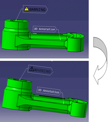
- For the texts displayed with the option “text parallel to screen”, the option is not taken into account at STEP export.
- For the Node Object Attribute (NOA) the filled areas are exported as
polylines representing the outline of the filled areas.
- The FTA features that are in the NoShow are exported in STEP
whatever the STEP Show/Noshow option state. By default the NoShow
geometry is not exported.
It can be exported optionally as NoShow STEP entities.
This behavior is not relevant for the FTA annotations because the visibility is an internal attribute used by the 3D Tolerancing & Annotation filtering capabilities.
When the FTA annotations are in a layer, this information is not preserved in the exchange. The use of captures for organizing the FTA annotations is recommended instead of layers.
The links enabling the cross highlight capabilities are not always preserved:
- The existing link between a datum and datum target is preserved:
- AP 242 is required.
- If the datum is not displayed in the native file, only the datum target is exported.
- The label of the datum and the datum target (within parentheses) is not preserved.
- When an annotation is linked to a vertex inside a solid or a surface, this link is not taken into account in the exchange.
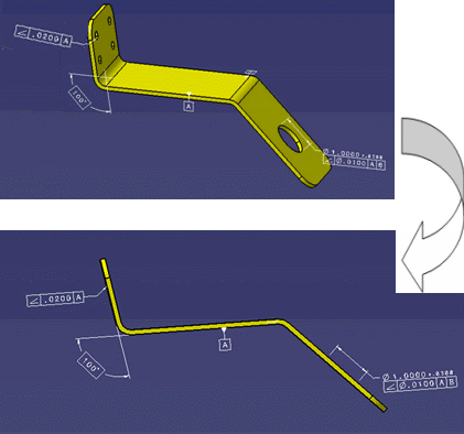
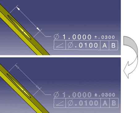
- When you pick a geometric tolerance, you do not highlight its referenced datum or dimensions (see example below).
- For an annotation pointing to a thread, the links between the
annotation and the thread are not managed at STEP export.
At import of the STEP file, the cross highlight does not work:- Initial model:
- after export/import:
- Initial model:
Capture STEP exchange limitations:
- The standard predefined camera that can be used for positioning the captures is not taken into account at export.
- A V5 capture works like a visualization filter defined
by
- The position of the camera
- The list of visible annotations
- The list of visible geometries. The geometries can only be from the constructed geometry, a geometrical set or a PartBody.
- Exchange of V5 captures supports Hide/Show of
geometry, with the following limitations:
- Hide/Show of tessellated geometry is not supported.
- Hide/Show of thread construction geometry is not supported.
- If no geometry is associated to the capture, all the geometries of the part are considered as visible in this capture.
- Geometrical set structuration is not preserved.
- When an annotation references an invisible geometrical entity not visible in any capture, the geometrical entity is not exported.
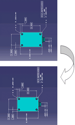
- A V5 capture can be associated with a clipping plane of the Part (generally the plane of the active view at its creation). The display capture function automatically activates the clipping plane in order to facilitate the review of the FTA of the capture. This clipping plane is managed for a single plane, in AP203 ed2 and AP242.
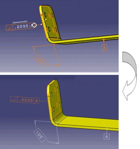
- The display capture function automatically displays FTA so that the texts are in the right sense to be read from the camera viewpoint. The FTA are reversed if needed (see example below in the red ellipse). This capability is not active for light FTA resulting from the STEP import.
- Example:
- Native part:
- Native part capture: This FTA is automatically reversed
according to the capture camera in the native part.
- STEP open capture: This FTA was not reversed according to the
capture camera in the STEP open part.
- Native part:
The FTA features and the Annotation set can be put in a layer. This information is not taken into account by the STEP exchange. The recommended practice for organizing FTA features is to use captures and not layers.
Construction geometry limitations:
At import, the construction geometry
is not imported as construction geometry in the Result Annotation set but in
a specific Geometric Set.
If you export again the imported CATPart in STEP,
the construction geometry is managed as standard geometry.
The 3D Annotation properties of the FTA are not taken into account in the exchange:
- The D&T feature name is the name of the set of geometrical entities involved in the geometrical link of the FTA.
- The standard representation displays the 2D annotation without arrows.
The Result Annotations are not modifiable and cannot be deleted.
If you create new annotations, they appear in a new regular annotation. Idem
if you create a view or a capture.
You cannot put a Result Annotation into a regular capture.
Double-click on a capture does not apply display capture.