|
This task shows you how to import to a CATPart or CATProduct
document
the data contained in a STEP file.
It is also possible to insert a STEP file as an existing component in a
CATProduct. |
 |


See also:
CAx Implementor Forum
http://www.cax-if.de
http://www.cax-if.org
|
|
|
Check the
license requirements for STEP! |
|
The table entitled What about the
elements you import ?
provides information on the entities you can import.
You can find further information in the Advanced Tasks:
and in the Customizing
STEP Settings chapter.
Statistics about each import operation can be found in the
report file and the error file.
|

|
-
Depending on your configuration:
Click the Open icon
 or select the File > Open command.
The File Selection dialog box is displayed. |
| or |
|
Insert/Existing component command.
The File Selection dialog box is displayed. |
-
Select one STEP format
from the list (*.step, *.stp, *.stpx, *.stpxZ,
*.stpZ).
*.stpx, *.stpxZ are STEP XML files.
*.stpxZ, *.stpZ are STEP compressed files.
All the files of the type selected are now displayed.
-
Select the file of your choice
(MoldedPart.stp, in our example) and click Open.
 |
| A progress bar is displayed. |
 |
You can use the Cancel button to interrupt the transfer at any
time.
The conversion is then interrupted (after the processing of the
current independent entity) and the partial conversion already
performed is displayed in the V5 session. |
|
|
|
What is then displayed depends on the contents of the STEP file.
- Compressed STEP files are uncompressed before
being imported.
- For the File/Open command:
- If the STEP file contains a normalized assembly structure,
a CATProduct document is created.
- If the STEP file does not contain any geometrical and
topological data,
the components will be visible only in the Specification Tree.
- If the STEP file contains also geometrical and topological data,
all the components will be present in the Geometry Space and in the
Specification Tree.
- If the STEP file contains only geometrical and topological data,
a CATPart document is created.
The geometrical elements of the faces, which could not be
transferred,
are created in the NO SHOW space. In the NO SHOW space, you can
visualize the Surface supports and the 3D Curves).
- For the Insert/Existing component command:
- if the STEP file contains no assembly information, it is
converted to a CATPart,
- if the STEP file contains assembly information, it is converted
to a CATProduct
referencing several CATPart documents.
The resulting document is inserted in the current CATProduct
document,
and the graphic window is updated (specification tree and geometry).
|
|
 |
- The reference to the STEP file is lost, so any update of the STEP file
will have no effect
in the CATProduct.
|
| |
- For both commands:
- The reference planes are hidden.
- A Geometrical Set is always created. It may be empty:
- it will contain the valid surfaces imported, if any.
- it is empty if there is no valid surfaces, e.g. when the element
imported is a solid,
or when all surfaces are invalid.
- invalid surfaces are sent to a specific Geometrical Set
(FaceKO#xxx)
|
|
Several STEP options can be customized:
-
Detailed report, to set the level of details of the transfer log,
-
Validation Properties,
to check the quality of the transfer,
-
Groups (Selection Sets), to activate/de-activate the transfer of
groups mapped with Selection Sets,
-
3D annotations,
to manage the V5 FTA,
-
Composites,
-
User
Defined Attributes, to manage the V5 knowledge parameters,
-
Continuity optimization of curves and surfaces, to optimize curves and
surfaces,
-
Assemblies physical structure,
-
Insert existing component,
-
Tessellated geometry.
|
|
 |
|
After the recovery of STEP files, the system generates:
-
a report file (name_of_step_file.rpt) where you
can find references about the quality of the transfer
-
and an error file (name_of_step_file.err) .
These files are created in a location referenced by the
CATReport variable. Its default value is
-
Profiles\user\Local
Settings\Application
Data\Dassault
Systemes\CATReport
on Windows (user being you logon id)
-
and $HOME/CATReport on UNIX.
|
|
|
Always check the report and
error files after a conversion !
Some problems may have occurred without been visually highlighted. |
|
|
Example of a report file
Note that the conversion summary in the report file takes
assemblies into account.

Legend
- OK = Transferred
- KO = Not Transferred
- NS = Unsupported
- OUT = Out Of Size
"OUT" entities are OUT of model size. Most of the time, these
entities are curves
and they are out of the V5 model space. These entities are not
created. |
- DEG = Degenerated
- "DEG" entities are degenerated entities. They are solids
(MANIFOLD_SOLID_BREP) or
Shells (OPEN_SHELL), or Curves (LINE, CIRCLE,...).
Degenerated solids are incomplete solids (at least one Face misses)
|
- INV = Invalid
"INV" entities are Invalid entities, that is to say their
description within the STEP file
is invalid (STEP syntax rules are not respected,...). These entities
are not created. |
|
|
Example of error file:
E:\Report\pm6-hc-214.err
Input FileName : G:\Equipe_STEP\STEP\PDES-Prostep\Tr8\Prod\pm6-hc-214.stp
Output FileName :
============================================
*** = Processing new independent element
* = Intermediate processing
!! = Independent element K.O.
! = Intermediate error
--------------------------------------------
<I> = Information
<W> = Warning
<E> = Error
--------------------------------------------
[0000] = Message identifier : 0000
[T=xxx] = Entity Type Step : xxx
[#0000] = Entity identifier number : 0000
============================================
Actual display level : Customer
|
| |
Report messages
|
| |
Here are some of the messages that may appear:
- Too many cuts on face boundary.
Tip : Use topological reduction option (in IGES) or curve optimization (in
IGES or STEP) - see User's Guide
These options are accessible via Tools/Options/Compatibility/STEP
dialog boxes, in
the Continuity optimization of curves and surfaces section.
Select the Advanced optimization option and push the
Parameters... button.
For more information, click on the link on STEP above.
- <W> [0904] The face #xx was splitted into nn CATIA V5 faces
This message indicates that a STEP face has been split into several
V5 faces to comply with V5 data structure.
|
| |
When the Continuity optimization of curves and
surfaces/Advanced
optimization option in
Tools/Options/Compatibility/STEP is active, the following warning
messages may appear in the report file:
- The BSpine Surface is not C1: Approximation of the surface is
impossible!
This is just a warning, the surface is imported but is not approximated.
- The deformation found of the surface approximation (which is
calculated by isoparameters) is : xx millimeters.
This indicates that the real deformation found is higher than the
Deformation value
you have entered in the Parameters box and that the
approximation could not be performed.
When this occurs for several entities, you will find the following
information message at the end of the report file:
- For a better approximation of BSpline surfaces, you can use a "Curves
and surfaces approximation"
Deformation value of at least : xx millimeters
You can enter this value in the Parameters box of the
Continuity optimization of curves and surfaces/Advanced
optimization option in Tools/Options/Compatibility/STEP.
|
| |
Assemblies
STEP files containing assembly structures can be imported.
STEP assemblies are mapped with the Product Structure. Geometry can be
defined:
- in STEP in the same file, or in STEP in external files (AP214/AP242
external references mechanism).
The files referenced are STEP files. External references are supported
with STEP AP214/AP203 edition2/AP242 only.
- or in CATIA in external files. The files referenced are CATIA files.
External references are supported with STEP AP214/AP203 edition2/AP242, but they are not with
STEP AP203.
- or by links to CATPart, model or cgr files via
Product_definition_with associated_document entities.
Assemblies generated by V4 CATASM and referencing to .model files or cgr
files are supported.
- Regarding STEP XML files, one stpx or stpxZ file
contains the structure referencing geometric files (external references
or nested assembly).
Geometric files can be *.stp, *.stpZ or .CATPart
files.
|
|
|
- The physical structure of an imported assembly can be defined by one
or several CATProducts (one for each node) depending of the option
selected.
(See the Assemblies physical structure option about the
import STEP files containing sub-assemblies).
- CATPart files are linked to the CATProducts as instances of Parts.
- Model files or cgr files are linked as Shapes.
- In the case of referenced files, those files must be in the same
location than the root STEP file, or be accessible via the search order.
- You can import of STEP assemblies into V5, even without any STEP
license. However, in this case, only the structure of the assembly is imported, not
the geometry.
The attributes of products are taken into account as follows:
| STEP |
|
V5 |
| PRODUCT.ID |
|
Part Number |
| PRODUCT.DEFINITION.ID |
|
Definition |
| PRODUCT.NAME |
|
Nomenclature |
| PRODUCT.DESCRIPTION |
|
Description |
|
PRODUCT_DEFINITION_FORMATION_WITH_SPECIFIED_SOURCE.MAKE_OR_BUY |
|
Source |
| PRODUCT_DEFINITION_FORMATION.ID |
|
Revision |
The attributes of instances of products are taken into account as
follows:
| STEP |
|
V5 |
| NEXT_ASSEMBLY_USAGE_OCCURRENCE.ID |
|
Component/Instance name |
| NEXT_ASSEMBLY_USAGE_OCCURRENCE.DESCRIPTION |
|
Component/Description |
|
|
|
Tessellated and Exact Geometry
The STEP Tessellated or exact geometry is linked to a STEP
product.
For each STEP product, a CATProduct is imported.
For a given STEP product, we can find both exact and tessellated
geometry linked to it; in this case, these representations are considered as
alternatives.
Transparency is supported by tessellated geometry.
Transparency is supported by exact geometry
(solids, shells and faces).
The transparency of a face of a solid can be
overloaded and is kept in the STEP file.
However, the transparency of an
instance cannot be overloaded.
With AP242 ed1,
|
|
|
Composites Data
When the
option is selected:
- The full stacking is kept: ply groups, sequences, plies,
cores, cut pieces are kept, as well as the contours,
orientations and materials, including their material
properties.
- Filament winding is not supported.
- STEP Composite Assembly Tables
containing ply laminates or Composite
Assembly constituents are not supported.
|
|
|
User Defined Attributes
The User Defined Attributes taken into account are:
- the Product: Added Properties (defined for a
CATProduct or a CATPArt),
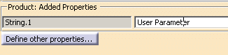
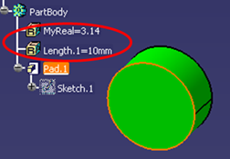
- the user parameters defined at the PartBody
level (i.e. associated to the solid it contains).
- The user parameters defined at surface feature level, contour
feature level and point feature level.
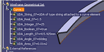
For each User Defined Attribute, STEP preserves:
- the name,
- the value (the formula is lost),
- the type of the parameter (string,
integer, real, boolean),
- the measure (when managed by STEP),
- the unit (when managed by STEP),
-
the association to a CATProduct or a PartBody.
If the STEP file contains a MEASURE_WITH_UNIT item, it is
imported as a string.
The mapping is as follows:
| Real |
NUMERIC_MEASURE (AP214) or
REAL_REPRESENTATION_ITEM (AP203 ed2/AP242 ed1) |
| Integer |
COUNT_MEASURE (AP214) or
INTEGER_REPRESENTATION_ITEM (AP203 ed2/AP242 ed1) |
| String |
DESCRIPTIVE_REPRESENTATION_ITEM |
| Boolean |
String with value TRUE or FALSE and an additional
meta-attribute specifying that the string UDA is a Boolean
(AP214)
or BOOLEAN_REPRESENTATION_ITEM (AP203 ed2/AP242 ed1) |
| Length |
MEASURE_REPRESENTATION_ITEM with name |
| Area |
MEASURE_REPRESENTATION_ITEM with
name |
| Volume |
MEASURE_REPRESENTATION_ITEM with name |
| Mass |
MEASURE_REPRESENTATION_ITEM with name
MASS_MEASURE (AP203 ed2/AP242 ed1) |
| Density |
MEASURE_REPRESENTATION_ITEM with name POSITIVE_RATIO_MEASURE (AP203 ed2/AP242 ed1) |
| Surfacic mass |
MEASURE_REPRESENTATION_ITEM with name POSITIVE_RATIO_MEASURE (AP203 ed2/AP242 ed1) |
| Time |
MEASURE_REPRESENTATION_ITEM with name
TIME_MEASURE (AP203 ed2/AP242 ed1) |
| Angle |
MEASURE_REPRESENTATION_ITEM with name
PLANE_ANGLE_MEASURE (AP203 ed2/AP242 ed1) |
| Energy |
MEASURE_REPRESENTATION_ITEM with name
ENERGY_MEASURE (AP203 ed2/AP242 ed1) |
| Force |
MEASURE_REPRESENTATION_ITEM with name
FORCE_MEASURE (AP203 ed2/AP242 ed1) |
| Pressure |
MEASURE_REPRESENTATION_ITEM with name
PRESSURE_MEASURE (AP203 ed2/AP242 ed1) |
| Temperature |
MEASURE_REPRESENTATION_ITEM with name
THERMODYNAMIC_TEMPERATURE_MEASURE |
| Power |
MEASURE_REPRESENTATION_ITEM with name
POWER_MEASURE (AP203 ed2/AP242 ed1) |
| Voltage |
MEASURE_REPRESENTATION_ITEM with name
ELECTRIC_POTENTIAL_MEASURE (AP203 ed2/AP242 ed1) |
| Electric resistance |
MEASURE_REPRESENTATION_ITEM with name
RESISTANCE_MEASURE (AP203 ed2/AP242 ed1) |
| Electric intensity |
MEASURE_REPRESENTATION_ITEM with name
ELECTRIC_CURRENT_MEASURE (AP203 ed2/AP242 ed1) |
| Luminous intensity |
MEASURE_REPRESENTATION_ITEM with name
LUMINOUS_INTENSITY_MEASURE (AP203 ed2/AP242 ed1) |
| Magnetic flux density |
MEASURE_REPRESENTATION_ITEM with name
MAGNETIC_FLUX_DENSITY_MEASURE (AP203 ed2/AP242
ed1) |
| Magnetic flux |
MEASURE_REPRESENTATION_ITEM with name
MAGNETIC_FLUX_MEASURE (AP203 ed2/AP242 ed1) |
| Mole |
MEASURE_REPRESENTATION_ITEM with name
AMOUNT_OF_SUBSTANCE_MEASURE (AP203 ed2/AP242 ed1) |
See also
Validation
Properties for User Defined Attributes.
In addition to the
License
Requirements for STEP, the following limitations apply:
- The following User Defined Attributes are not managed by STEP:
- constant: value not modifiable is selected.
- hidden: visibility in the specification tree.
- comment.
|
|
|
Groups
- For each APPLIED_GROUP_ASSIGNMENT pointing to a group and a list of
entities in the STEP file,
a Selection Set is created. This Selection Set is named with the
name of the pointed GROUP entity
and includes all pointed entities.
- The transfer of groups can be activated/de-activated via the
Groups (Selection Sets) option.
Layers
The number of the layer imported is defined by STEP
PRESENTATION_LAYER_ASSIGMENT.ID. This is a string representing an integer.
If this integer is higher than 1000, the number of layer will be imported as
0. Annotations
See
About 3D Annotations in Graphic Mode and
About 3D Annotations in Authorable and Graphic Mode.
Axis systems described as supplemental geometry in the STEP file are
imported in V5 as standard axis systems with
coordinates as parameters.
Axis systems are supported by STEP AP214/AP203 edition2/AP242
The STEP name of the axis system is used for defining the name of
the axis system in the specification tree.
The visibility of the axis system is taken into account like for
the other geometrical elements (according to the Show option).
The summary in the report file takes the exchange of Axis System into
account. |
|
|
|
|
|
Infinite Planes
Infinite planes described as supplemental geometry in the STEP file are
imported in V5.
Infinite planes are supported by STEP AP214/AP203 edition2/AP242.
The STEP name of the plane is used for defining the name of the plane in
the specification tree.
The visibility of the plane is taken into account like for the other
geometrical elements (according to the Show option).
Note: When importing a STEP file, three default planes are created
automatically in the NoShow in the CATPart.
|
|
Shape Representation |
geometrically
bounded
wireframe |
geometrically
bounded
surface |
edge-based
wireframe |
shell-based
wireframe |
manifold
surface |
faceted
brep |
advanced
brep |
|
High Level Entities |
geometric_curve_set |
geometric_set |
edge_based_
wireframe_model |
shell_based_
wireframe_model |
shell_based_
surface_model |
faceted_brep
brep_with_voids |
manifold_solid_brep
brep_with_voids |
|
Entity |
 |
|
Point |
cartesian_point |
I |
I |
I |
I |
I |
NI |
I |
|
point_on_curve |
NI |
NI |
N/A |
N/A |
NI |
N/A |
N/A |
|
point_on_surface |
N/A |
N/A |
N/A |
N/A |
NI |
N/A |
NI |
|
point_replica |
NI |
NI |
NI |
NI |
N/A |
N/A |
NI |
|
degenerate_pcurve |
N/A |
N/A |
N/A |
N/A |
NI |
N/A |
NI |
| |
|
Curve |
line |
I |
I |
I |
I |
I |
N/A |
I |
|
circle |
I |
I |
I |
I |
I |
N/A |
I |
|
ellipse |
I |
I |
I |
I |
I |
N/A |
I |
|
hyperbola |
I |
I |
I |
I |
I |
N/A |
I |
|
parabola |
I |
I |
I |
I |
I |
N/A |
I |
|
polyline |
I |
I |
I |
I |
I |
N/A |
I |
|
b_spline_curve (+ rational)
b_spline_curve_with_knots |
I |
I |
I |
I |
I |
N/A |
I |
|
uniform_curve (+rational) |
NI |
NI |
NI |
NI |
NI |
N/A |
NI |
|
quasi_uniform_curve (+rational) |
I |
I |
I |
I |
I |
N/A |
I |
|
bezier_curve |
I |
I |
I |
I |
I |
N/A |
I |
|
trimmed_curve |
I |
I |
N/A |
N/A |
N/A |
N/A |
N/A |
|
composite_curve |
I |
I |
N/A |
N/A |
N/A |
N/A |
N/A |
|
composite_curve_on_surface |
N/A |
NI |
N/A |
N/A |
N/A |
N/A |
N/A |
|
boundary_curve
outer_boundary_curve |
N/A |
NI |
N/A |
N/A |
N/A |
N/A |
N/A |
|
pcurve |
NI |
N/A |
N/A |
N/A |
NI |
N/A |
NI |
|
surface_curve |
I |
N/A |
N/A |
N/A |
|
N/A |
|
|
offset_curve_3D |
NI |
N/A |
NI |
NI |
NI |
N/A |
NI |
|
curve_replica |
NI |
N/A |
NI |
NI |
NI |
N/A |
NI |
| |
|
Surface |
plane |
N/A |
I |
N/A |
N/A |
I |
NI |
I |
|
cylindrical_surface |
N/A |
I |
N/A |
N/A |
I |
N/A |
I |
|
conical_surface |
N/A |
I |
N/A |
N/A |
I |
N/A |
I |
|
spherical_surface |
N/A |
I |
N/A |
N/A |
I |
N/A |
I |
|
toroidal_surface |
N/A |
I |
N/A |
N/A |
I |
N/A |
I |
|
degenerate_toroidal_surface |
N/A |
I |
N/A |
N/A |
I |
N/A |
I |
|
surface_of_linear_extrusion |
N/A |
I |
N/A |
N/A |
I |
N/A |
I |
|
surface_of_revolution |
N/A |
I |
N/A |
N/A |
I |
N/A |
I |
|
b_spline_surface
b_spline_surface_with_knots |
N/A |
I |
N/A |
N/A |
I |
N/A |
I |
|
uniform_surface |
N/A |
NI |
N/A |
N/A |
NI |
N/A |
NI |
|
quasi_uniform_surface |
N/A |
I |
N/A |
N/A |
I |
N/A |
I |
|
bezier_surface |
N/A |
I |
N/A |
N/A |
I |
N/A |
I |
|
rectangular_trimmed_surface |
N/A |
I |
N/A |
N/A |
N/A |
N/A |
N/A |
|
curve_bounded_surface |
N/A |
I |
N/A |
N/A |
N/A |
N/A |
N/A |
|
rectangular_composite_surface |
N/A |
NI |
N/A |
N/A |
N/A |
N/A |
N/A |
|
offset_surface |
N/A |
I |
N/A |
N/A |
I |
N/A |
N/A |
|
surface_replica |
N/A |
NI |
N/A |
N/A |
NI |
N/A |
N/A |
|
|
Topology |
vertex_point |
N/A |
N/A |
I |
I |
I |
N/A |
I |
|
edge_curve |
N/A |
N/A |
I |
I |
I |
N/A |
I |
|
oriented_edge |
N/A |
N/A |
N/A |
I |
I |
N/A |
I |
|
vertex_loop |
N/A |
N/A |
N/A |
NI |
NI |
N/A |
NI |
|
poly_loop |
N/A |
N/A |
N/A |
NI |
N/A |
NI |
N/A |
|
edge_loop |
N/A |
N/A |
N/A |
I |
I |
N/A |
I |
|
face_bound
face_outer_bound |
N/A |
N/A |
N/A |
N/A |
I |
NI |
I |
|
face_surface |
N/A |
N/A |
N/A |
N/A |
I |
I |
N/A |
|
advanced_face |
N/A |
N/A |
N/A |
N/A |
I |
NI |
I |
|
oriented_face |
N/A |
N/A |
N/A |
N/A |
NI |
N/A |
N/A |
|
vertex_shell |
N/A |
N/A |
N/A |
NI |
N/A |
N/A |
N/A |
|
wire_shell |
N/A |
N/A |
N/A |
NI |
N/A |
N/A |
N/A |
|
connected_edge_set |
N/A |
N/A |
I |
N/A |
N/A |
N/A |
N/A |
|
open_shell |
N/A |
N/A |
N/A |
N/A |
I |
N/A |
N/A |
|
oriented_open_shell |
N/A |
N/A |
N/A |
N/A |
N/A |
N/A |
N/A |
|
closed_shell |
N/A |
N/A |
N/A |
N/A |
I |
NI |
I |
|
oriented_closed_shell |
N/A |
N/A |
N/A |
N/A |
N/A |
NI |
I |
|
manifold_solid_brep |
N/A |
N/A |
N/A |
N/A |
N/A |
N/A |
I |
|
brep_with_voids |
N/A |
N/A |
N/A |
N/A |
N/A |
N/A |
I |
|
faceted_brep |
N/A |
N/A |
N/A |
N/A |
N/A |
I |
N/A |