| |
Creating Corner Fillets
|

|
| |
Creating a Ball Corner
|
|
 |
Open the CornerFillet_ball.CATPart document. |
 |
-
Click the Corner Fillet icon
 . .
The Corner Fillet dialog box opens.
|
 |
| |
-
Select Ball in the Corner Type list box.
|
|
| |
-
Select the elements Advanced Fillet.1 to 3.
|
 |
| |
-
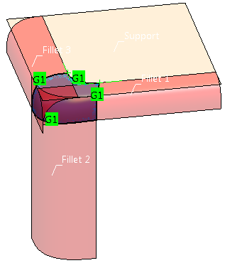
Select G1 continuity for all three fillet surfaces.
-
Specify a Ball Radius of 20mm.
-
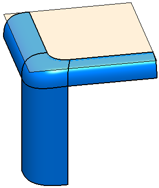
Click Apply to create the ball corner.
|
 |
| |
-
Select the Trim Fillet buttons for Fillet 1 to 3 to trim the fillet surfaces at the created ball corner.
-
Click OK to create the ball corner and terminate the command.
|
 |
| |
Creating a Blend Corner
|
|
|
Open the CornerFillet_blend.CATPart document. |
| |
-
Select Blend in the Corner Type list box.
|
|
| |
-
Select the elements Advanced Fillet.1 to 3.
-
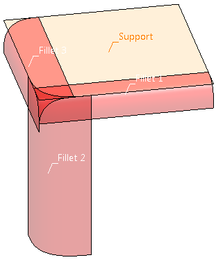
Select the element Support.
|
 |
| |
-
Specify 15mm for Length 1 and Length 2 for both sides of Curve 1.
-
Select G1 continuity for all three fillet surfaces and the support.
-
Click Apply to create the blend corner.
|
 |
| |
-
Select the Trim Fillet buttons for Fillet 1 to 3 to trim the fillet surfaces at the created blend corner.
-
Click OK to create the blend corner and terminate the command.
|
 |
| |
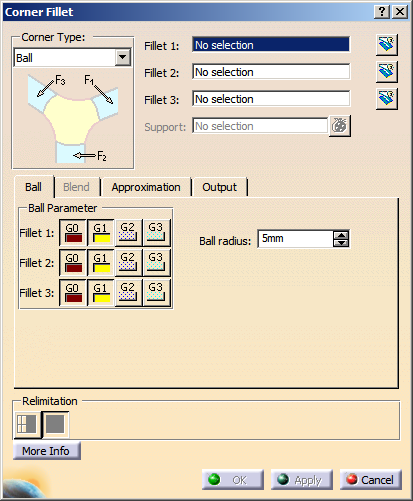
The Dialog box Corner Fillet
|
|
 |
You can define the following options:
Corner Type
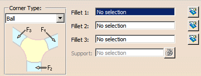
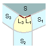
- Ball
In the corner is positioned a ball with a specified radius. The connecting surfaces between ball and fillets form the ball
corner, thus ensuring that the minimum radius is directly applied on the ball surface.
For this corner type must be selected as input elements three fillet surfaces created with the Advanced
Fillet command. No other input type is accepted as valid input, i. e. Styling Fillet or Tri-tangent Fillet features.
If the corner type Ball is selected, the input boxes Fillet 1 to Fillet 3 are displayed.
For each box only one existing Advanced Fillet feature can be selected.
The Support option is not available.
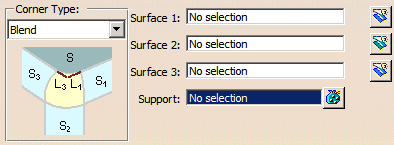
- Blend
The corner fillet consists of four edges. Three of them are the trimmed fillets and the fourth edge is connected to a basic
surface.
For this corner type three fillet surfaces of any type can be selected as input elements.
If the Corner Type Blend is selected, the input boxes Surface 1 to Surface 3 are displayed.
For each input box only one surface can be selected.
The Support option is available for the selection of one or several support surfaces.
|
 |
Note: As for the corner type Ball, the input is more restrictive as for the corner type
Blend, all unusable input elements are removed from the selection when switching from Blend to Ball. A warning dialog
box is displayed where you can choose between
- Yes, to switch to the corner type Ball and loose all unusable inputs, or
- No, to stay in the current mode and preserve all inputs.
The selection removed when switching to the corner type Ball will not be restored when switching back to Blend. |
| |
- Fillet 1-3: Selects input elements for Ball.
- Surface 1-3: Selects input elements for Blend.
 Trim: Fillet/Surface
1-3 are trimmed at the appropriate edge of the corner fillet. Trim: Fillet/Surface
1-3 are trimmed at the appropriate edge of the corner fillet.- Support: Only available for Blend.
Selects the common support surface of Surface 1 and Surface 3 for the blend corner creation.
- Relimitation: The fillet surface can be trimmed in two different ways. The fillet surface is the basic surface
for the trim operation.
 Trim
Face: The basic surface remains unchanged. The result is a face. Trim
Face: The basic surface remains unchanged. The result is a face. Trim Approx:The
basic surface changes. The result is not a face. Trim Approx:The
basic surface changes. The result is not a face.
|
| |
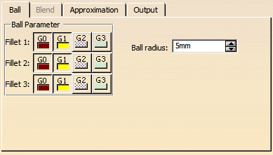
Ball tab |
 |
| |
The Blend tab is not available. |
| |
- Ball Parameter: Specifies individual continuity conditions between the ball corner and the fillet supports.
- Ball radius: Defines the size of a theoretical ball which touches all three selected support fillets.
The smaller the value the shaper the Ball corner will be, the larger the value the smoother the Ball corner will be.
|
| |
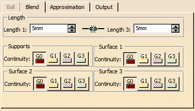
Blend tab |
 |
| |
The Ball tab is not available. |
| |
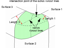
- Length: The Length options define the blend edge of the corner fillet between two fillet surfaces
used as support. As default, the edge between fillet 1 and 3 opposite to fillet 2 is defined as Length.
- Length 1 / Length 3: Length 1 and 3 derive from the distance between the intersection
point of the radius runout lines (RRL) of Surface 1 and 3 and the upper corner points of the corner fillet surface. For
each side can be specified an individual length.
Example: A blend shape for Length is defined by Length 1 = 5mm and Length 3 = 10mm.
- Supports, Surface 1-3 – Continuity: Defines the continuity between the created corner fillet and Supports and
Surface 1 to 3, respectively.
|
| |
See Approximation tab |
| |
See Output tab |
| |
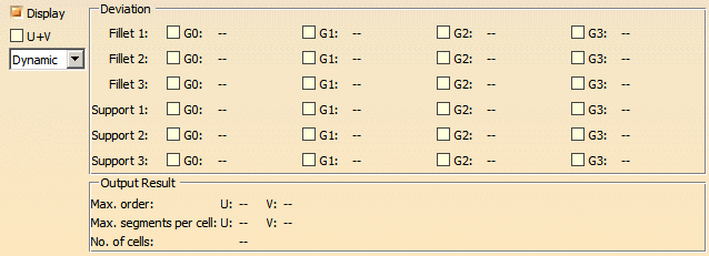
Click 'More Info' to display deviations and output results. |
Deviation analyses for Corner Type Ball result:
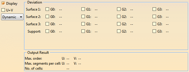
Deviation analyses for Corner Type Blend result:
 |
|
- Display: Depending on the options selected, values are displayed in the graphics area.
- U+V: Display of the U+V vectors of curves and surfaces.
- Dynamic, Static, None: See Apply Modes
- Deviation:
- Corner Type Ball:
- Fillet 1-3: Displays the maximum G0 to G3 deviation of the created corner fillet from the input fillet
surfaces Fillet 1-3.
- Support 1-3: Displays the maximum G0 to G3 deviation of the created corner fillet from the support surfaces
of the input fillet surfaces.
- Corner Type Blend:
- Surface 1-3: Displays the maximum G0 to G3 deviation of the created corner fillet from the input
Surface 1-3.
- Support: Displays the maximum G0 to G3 deviation of the created corner fillet from the
Support.
- Output Result: See Output Result
|
|
Manipulators
|
| |
For a corner fillet modification of the Blend corner type, the following manipulators
are available:
- Point manipulators: Modify start and end position of Curve 1 (see Length 1 / Length 2).
- Tension manipulators: Modify the shape of Curve 1.
- Continuity manipulators: To set the different continuities, continuity manipulators are available on the
Blend corner fillet boundaries.
|
|

|
| |
Concept
|
|
 |
Within the complex discipline of Class A surface modeling of automotive interior or exterior components, it is
often the case that the modeling completion of components is done via the filleting together of two sets of surfaces. This is
a common practice which is in most cases a simple operation in which to perform.
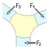
However, when three fillets converge at a single point of intersection, there is often a styling requirement to blend out the
intersections to generate a more aesthetically pleasing result. This fillet convergence is often a more complex situation in which
to create a solution as today the process is manual.
The command Corner Fillet allows the creation of Class-A quality corner fillets with a single command. |
| |
Ball Corner
|
|
| |
The traditional corner fillet is the ball corner derived from three fillets of circular roundnesses created with
the Advanced Fillet command. However, to adhere to manufacturing and legal requirements, frequently
a minimum radius for the corner fillet is required.
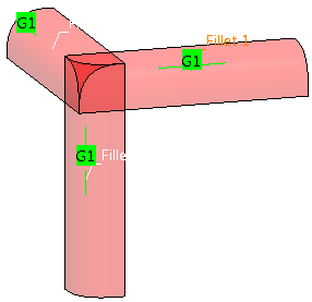
The following images describe an example of a more manual approach to create a traditional Ball Corner scenario from three fillets
having the same radius value of 10mm converging and intersecting at a single point. |
 |
|
The image on the right shows the three fillets having been trimmed to their intersection to demonstrate the point
at which the Ball Corner fillet must be inserted. |
 |
| |
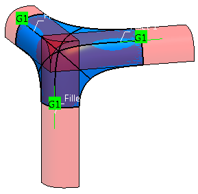
One of the more traditional manual methods to generate a Ball Corner fillet is to trim back the supporting fillets
to their intersection with adjacent fillets. Thus creating a hole in which to create the corner. |
 |
| |
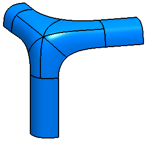
The final stage is to create the Ball Corner fillet using either alternative commands such as Surface Creation
> Fill or Surface Creation > Patch from Curves or to start from a
flat patch and by using control points and Matching create a result meeting Class A standards. |
 |
| |
Blend Corner
|
|
| |
Following on from the more traditional Ball corner fillet, another type of corner fillet commonly required is
a Blend Corner fillet.
Like the Ball Corner, the Blend Corner is commonly derived from three converging fillets. However, unlike the Ball corner, the
requirement is to blend out the shape of the fillet between the three intersecting fillets which may be of differing sizes.
The blending of the corner fillet will of course needs to fulfill the correct Class A, manufacturing and legal requirements, but
is very much a design feature depicted by what aesthetically provides the best result.
Very often its construction is complex and time consuming to complete, and the techniques used in its creation vary between users.
The following images outline a number of steps commonly used in such construction techniques.
|
| |
The image on the right shows the three fillets having been trimmed to their intersection to demonstrate the point
at which the Blend Corner fillet must be inserted. |
 |
| |
One of the next steps is to create the blend curves which define the main shape of the Blend Corner and limiting
curves in which to trim back the supporting fillets. Thus creating a hole in which to create the Blend corner. |
 |
| |
The final stage is to create the Blend Corner fillet using either alternative commands such as Surface Creation
> Fill or Surface Creation > Patch from Curves or to start from a
flat patch and by using control points and Matching create a result meeting Class A standards. |
 |