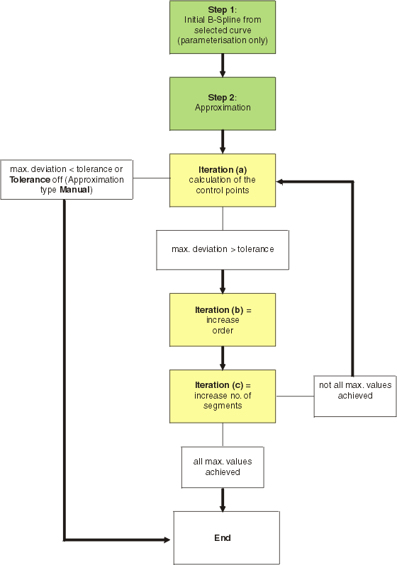
The approximation is computed in two steps:
- Creation of an initial B-Spline
With the first step, for each selected curve is created an initial B-Spline, defining the parameterization and the number of control points, but not their values. The B-Spline results from the B-Spline of the curve to be approximated as well as from the minimum and maximum values of the order and the number of segments specified by the user:
Order and number of segments of the B-Spline are taken from the curve to be approximated, if they are within the specified minimum and maximum ranges. Otherwise, they are increased or reduced to the corresponding minimum or maximum value.

Note: If in the selected geometry G2 discontinuities are found, they are transferred as sharp bends to the initial B-Spline. In this case, the initial B-Spline may contain more segments than the maximum value specified for the Segmentation. - Iterations
After the creation of the initial B-Spline, the actual approximation is computed in the second step. This is realized by a three-step iteration:
- Iteration (a)
In the first iteration, the (optimal) values of the control points of the B-Spline are computed using a Newton method. The control points allow the computation of the maximum deviation between the computed approximation curve and the original curve. If this value is smaller than the tolerance value specified by the user, the iteration is terminated successfully.
- Iteration (b) + (c)
If the computed deviation is larger than the tolerance specified, the B-Spline will be modified by increasing order and number of segments, and the iteration (a) is restarted.
Independent from the approximation type set, first the order and then the number of segments is increased. This way, the number of segments of the created curves can be minimized.
- Iteration (a)
Structure view of the approximation


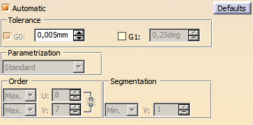
- Automatic:
- ON: Tolerance G0, Smoothing, Order, and Segmentation are
disabled.
Only Tolerance G1 and Parametrization can be specified.
For Order and Segmentation, internally preset values are used. - OFF: All options are available and can be modified manually.
- ON: Tolerance G0, Smoothing, Order, and Segmentation are
disabled.
Only Tolerance G1 and Parametrization can be specified.
- Defaults: If this button is selected, all approximation parameters currently available and selected in the corresponding
command are overwritten with default values defined on the
Approximation tab in Tools > Options > Shape > ICEM Shape Design. Afterwards, you can reedit the values, if necessary.

Note: In commands where only V Segmentation can be defined, the V default value is read when selecting Defaults independently from the link  setting on the Tools > Options Approximation
tab.
 - Tolerance: The tolerance value defines the accuracy in which the output geometry should
be created.
- G0: With the check button G0 the influence of the G0 tolerance can be controlled as follows:
- ON:
a) Provided that for Order and Segmentation the maximum and minimum values specified allow increasing the order, these values are increased iteratively until the deviation between the input geometry (or the theoretical results) and the approximation result exceeds the value of the G0 tolerance.
b) The value of the G0 tolerance is also available for the computation to create the theoretical results. - OFF: The value of the G0 tolerance is now also available for the computation to create the theoretical results, i. e. the tolerance value can be edited in the text field and thus may also influence the result.
- ON:
- G1: The G1 tolerance is only available in commands, in which angle deviations can occur, e. g.
Advanced Fillet.
With the G1 tolerance the maximum angle deviation between final and theoretical result is specified. This shall guarantee that the angle between final result and selected support does not exceed the value of the G0 tolerance.
- G0: With the check button G0 the influence of the G0 tolerance can be controlled as follows:
- Parametrization:
- Standard: No re-parametrization of the result is performed. The parameter flow of the approximation is the same as that of the input curve.
- Adapt: Behaves like Standard if the selected input curve is a space curve.
If the selected input curve is a surface curve the parameter flow will be adapted either to the parametrization of the surface curve's basic surface's u- or v-direction.

Attention!
If the curve does not unambiguously run in U or V direction, or if it changes the direction from to V or vice versa,
this option will not produce a result! - Arc Length: The curve is re-approximated with a parametrization which is computed according to the arc length between parametrically equidistant curve points. (The curve arc length between each pair of equidistant parameters (approximately) has same value.)
- Smoothing: This option allows the desired compromise between an exact approximation and
a very smooth curve.
By using this option the function tries to equally distribute the control points of the resulting geometry. - Order:
- Min.: The order of the selected geometry being below this value is increased until it reaches this value.
For the approximation the order can be increased until 7 at maximum. - Max.: The order of the selected geometry being above this value is reduced until it reaches this value.
For the approximation the order cannot exceed this value. - Fix: Increase and/or decrease the order of all selected elements until it meets exactly the order specified
here.
For the approximation, the order cannot have another value than the specified one. - Inp. (Input): If this method is activated, the patch is computed cell by cell and order-wise. The order in U and V direction is taken from the generating curves (guides).
- Min.: The order of the selected geometry being below this value is increased until it reaches this value.
- Segmentation:
- Min.: Increase the number of segments of the selected geometry which is below this value until it reaches
this value.
For the approximation the number of segments can be arbitrarily increased. - Max.: The number of segments of the selected geometry being above this value is reduced until it reaches
this value.
For the approximation the number of segments cannot exceed this value. - Fix: Increase and/or decrease the segmentation of all selected elements until it meets exactly the segmentation
specified here.
For the approximation, the number of segments cannot have another value than the specified one.
Note: If in the selected geometry G2 discontinuities are found, they are transferred as sharp bends.
In this case, the result may contain more segments than the maximum value specified Segmentation: Max. or Fix.
- Min.: Increase the number of segments of the selected geometry which is below this value until it reaches
this value.