|
Open the PatchFromCurves.CATPart document. |
 |
-
Click the Patch from Curves icon
 . .
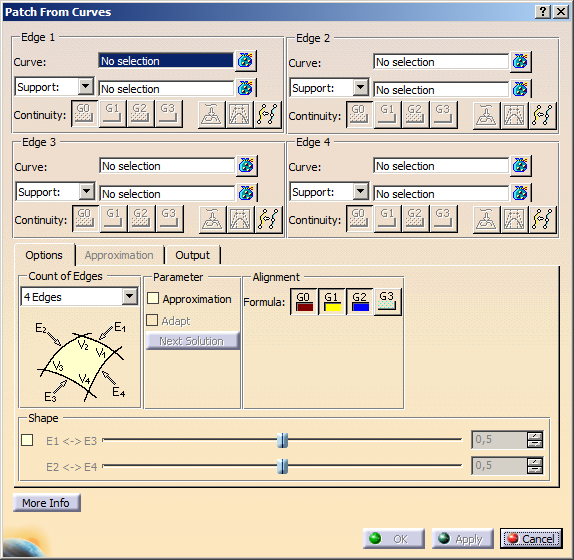
The 'Patch from Curves' dialog box is displayed.
|
 |
| |
-
Select curve 1.
|
 |
| |
-
Click in the selection field Curve for Edge 2 and select curve 2, and repeat this for
Edge 3 and Edge 4.
|
 |
| |
-
Change the Continuity if required.
|
|
| |
-
Click Apply to create the new surface.
|
|
 |
You can define the following options:
Definition of the Edges 1 - 4
- Curve: Selection of 2 to 4 edges.
Depending upon the Count of Edges option, after each curve is selected, the next Curve
input field is automatically activated.
- Support: Selection of a support surface to influence the shape of the surface.
- Surface curve/edge is selected: The surface is automatically selected as support.
- 3D curve is selected: By default, no support is chosen.
After each surface is selected, the next Curve input field is automatically activated to await an input.
 |
Note: For the input of the support surface, the following criteria must be met:
- The selection of multiple surfaces is allowed for each support input.
- Support surfaces are NOT preprocessed as PrepareSurfaces.
- The edge curve must NOT completely be projectable.
- The edge curve must be projectable onto the support when the Curve Projection option is chosen.
- The surfaces must cover the extents of the selected edge curve.
- Only one domain is accepted as valid input for support surfaces.
|
- Symmetry: Selection of a symmetry plane.
- Continuity: G0 - G3 (G3 in ISD only): Definition of the continuity condition for the selected edge curves
and support surfaces.
- 3D curve is selected: The continuity is set to G0 (position) continuity and cannot be increased without selecting
a support surface.
- Surface curve is selected: The continuity is set to G0, but can be increased, either via the appropriate option
in the dialog box, or via the continuity manipulator on the curve in the graphics.
 Curve Projection :
If this option is switched on, the selected curves are projected normal onto support and then used as edges. Curve Projection :
If this option is switched on, the selected curves are projected normal onto support and then used as edges.
Information for higher continuity is taken from support.
| Curve Projection: default setting OFF |
 |
 Adapt/Linear
Connection : The first internal control point row of the result surface can be linearly aligned with the adjacent
support surface(s). Adapt/Linear
Connection : The first internal control point row of the result surface can be linearly aligned with the adjacent
support surface(s).
|
Note:
- An alignment is only possible if the projected curve is nearly an isoparametric surface curve.
- If at least G1 is required, the control points of the second row are calculated with respect to the cross parameter
direction of the approximated isoparametric surface curve. There is NO control point based alignment.
- The edge is using the parametrization of the corresponding surface parameter direction if Approximation
is ON and no contradictory switches are set.
|
| Adapt/Linear Connection OFF |
 |
| Adapt/Linear Connection ON |
 |
| |
| |
 Reparametrization (in ISD only): If this
option is set for an edge, the parametrization at this edge is derived from the opposite edge. Reparametrization (in ISD only): If this
option is set for an edge, the parametrization at this edge is derived from the opposite edge.
|
Note: This option has no effect, if the opposite edge is not defined. It is impossible to
activate this option for opposite edges simultaneously. |
|
|
'Options' tab |
 |
| |
- Count of Edges : Number of edge curves to be used for the surface creation.
 |
2 Edges |
Edge 1 and 2 selection fields are available. |
 |
3 Edges |
Edge 1, 2, and 3 selection fields are available. |
 |
4 Edges |
Edge 1, 2, 3, and 4 selection fields are available. |
- Parameter
- Approximation: Parametrization of the surface.
- OFF: Order and segmentation of the input curves are used for the result surface.
|
Note: Adoption of segmentation and order is only possible if the selected curves are Bezier
or BSpline. |
- ON: Order and segmentation of the result surface can be influenced via the options on the 'Approximation'
tab.
- Adapt: With this option, you may determine how the additional edge(s) will be created.
- OFF: The edge(s) will be created as straight line.
- ON: The edge(s) will be created by adjusting the opposite edge. This is done by carrying out a translation
and rotation.
| 2 edges |
3 edges |
 |
 |
- Next Solution : Alternate between possible solutions.
|
Note: The option is only possible if 2 or 3 edges are selected. |
- Alignment: Formula: According to setting the option Adapt/Linear Connection,
this option has the following effect at the associated edge:
- Adapt/Linear Connection OFF: Option Formula has no effect. In this case, always normal projection of control
points is applied. A smooth control point distribution will be achieved, but an exact calculation cannot be guaranteed.
- Adapt/Linear Connection ON for the neighbored edge: This edge defines the position of shared control
points regarding required alignments (twist alignment). This method permits a more exact calculation, but the control
point alignment will possibly not be smooth enough.
The following settings can be made:
- G0
- G1 alignment is already applied via normal projection of control points of initial G0 connected surface.
- G2 and G3 alignments are also applied via normal projection method.
- Exact G1 matching is impossible.
- G0+G1
- G1 alignment is applied via a mathematical formula approach.
- G2 and G3 alignments are applied via normal projection method.
- Exact G2 matching is impossible.
- G0+G1+G2
- G1 and G2 alignments are applied via formula approach.
- G3 alignment is applied via normal projection method.
- Exact G3 matching is impossible.
- G0+G1+G2+G3 (G3 in ISD only)
- All alignments (G1, G2, and G3) will be evaluated via formula approach.
- Control points will be evaluated with respect to all sides simultaneously.
- Control point propagation is given via formulas.
- Exact matching is possible, if input is perfect.
Default Setting is G2.
- Shape: With these sliders you can shape the surface depending on the shape of the boundary curves. One
surface edge is given more influence than the opposite edge. Values between 0.1 and 0.9 are allowed.
|
| |
See 'Approximation' tab |
|
| |
See 'Output' tab |
|
| |
Click 'More Info' to display deviations and output results. |
 |
| |
- Display: Depending on the options selected, values are displayed in the graphics area.
- U+V: Display of the UV vectors of curves and surfaces.
- Static, None: See Apply Modes
- Deviation:
- Check buttons: The individual deviations can be displayed also in the graphics.
- Edge 1 - 4 : Maximum deviation (G0) between the edges of the result surface and the (projected) input curves;
if additional supports are selected, also G1, G2, and G3 deviations.
- Vertex 1 - 4 : Position distance (G0) for any contact point between two selected (projected) curves; if additional
supports are selected, also normal deviation (G1) and twist deviation (T1).
- Output Result: See Output Result
|