- Available in Composites Engineering Design (CPE) and Composites Design for Manufacturing (CPM).
- Some Propagation modes, Deformation options, Simulation: Advanced Parameters, and Analysis: Advanced Parameters are available only if Composites Fiber Modeling (CFM) is available. See details below.
- In a few cases, the position of seed points may lead to an invalid rosette transfer and incorrect fiber directions. The problem is detected as you click Preview, and a warning is displayed.
Go to Tools > Options > Mechanical Design > Composites Design to define the Producibility default behavior.
-
Click Producibility for Fiber Placement
 in
the Flattening toolbar.
in
the Flattening toolbar.
The Producibility for Fiber Placement dialog box opens at the Home tab. -
Select the ply to process.
It is highlighted in the graphic area.
The Home tab is activated.
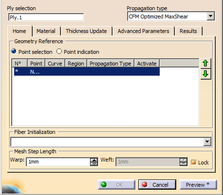
Select the Propagation type from the list.
- If Composites Fiber Modeling is not available,
proposed types are:
- Minimum distortion
In the above picture, the shape of the surface is not symmetrical. On this non-symmetrical shape, the fiber propagation with the Minimum Distortion option follows the curvatures of the surface while minimizing the deformation of the fibers. - Symmetric
With the Symmetric option, the system forces the fiber propagation to be symmetrical.
- Minimum distortion
- If Composites Fiber Modeling is available, proposed
types are:
- Minimum distortion
- Symmetric
- CFM Optimized Energy
- CFM Optimized MaxShear
- CFM Tape
- CFM UD Tape
- CFM FEFlatten.
See Propagation Type for more information.
- If Composites Fiber Modeling is not available,
proposed types are:
-
Select seed points, that is points used to start the propagation of the fibers.
- Select Point selection and pick an existing point that lies on the surface, within the external countour of the ply.
- Should you need to create one, right-click in the table below and use the contextual menu to create one.
- Alternatively, select Point indication and pick where you would create a seed point, within the boundaries of the selected ply. This allows a quicker analysis of the producibility as you can restart the analysis with another point without creating one.
-
Define regions or sectors for each tape or tow in the table under Geometry Reference.
- If Composites Fiber Modeling is available, the N°, Point, Curve, Region, Propagation Type and Activate columns are available.
- If Composites Fiber Modeling is not available, only the N°, Point, Propagation Type and Activate columns are available.
- The last line of the table is dedicated to the creation of a New Sector.
-
Select New Sector and select or indicate points as explained above.
A new sector is created and activated. -
Use the available contextual menus to modify the input:
- For N°, Point and
New Sector:
- Create Point
- Create Midpoint
- Create Endpoint
- Create Intersection
- Create Projection
- Create Extremum
- Create Extract
- Clear Sector
- Clear Cell
- For Curve and Region:
- Create Line
- Create Intersection
- Create Projection
- Create Parallel Curve
- Create Isoparametric Curve
- Create Spline
- Create Join
- Create Boundary
- Create Extract (in point)
- Create Extract (in tangency)
- Create Multiple Extract
- Create Curve Smooth
- Clear Sector
- Clear Cell
- For Propagation Type:
- If Composites Fiber Modeling is not available
- Clear Sector
- Clear Cell
- Minimum distortion
- Symmetric
- If Composites Fiber Modeling is available
- Clear Sector
- Clear Cell
- Minimum distortion
- Symmetric
- CFM Optimized Energy
- CFM Optimized MaxShear
- CFM Tape
- CFM UD Tape
- CFM FE Flatten
- If Composites Fiber Modeling is not available
- For Activate:
- Clear Sector
- Activate
- Deactivate
- For N°, Point and
New Sector:
-
When available, select a Fiber Initialization from the list.
-
Define the Warp and Weft values for the fiber meshes.
Warp is the radius used to simulate the fiber behavior along the X-Axis, Weft is the radius used to simulate the fiber behavior along the Y-Axis. -
Refer to Creating a Producibility for Hand Layup for the Material, Thickness Update, Advanced Parameters and Results tabs.
-
Click OK to validate and exit the dialog box.
Producibility parameters (i.e. seed point, warp and weft) are now stored as Producibility params.x under each ply, and may be later used when flattening plies.
Existing producibility parameters sets are kept. -
Use the producibility parameters contextual menu to edit them, or activate them, or mark them as not usable for manufacturing.
![]()