once you are satisfied with the Producibility analysis result of the seeds behavior.
![]()
See About Rosette Transfer for more information.
Flattening processes only entities that have producibility parameters.
-
Click Flattening
 in the Flattening toolbar.
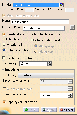
The Flattening dialog box appears.
Select the feature to flatten.
- It can be a ply, a ply sequence, a plies group or a stacking.
- Multi-selection of entities
 is available.
 - In the dialog box that appears,
 gives access to the
Stacking Management.
gives access to the
Stacking Management. - The numbers of plies and cut-pieces are computed and displayed in the dialog box.
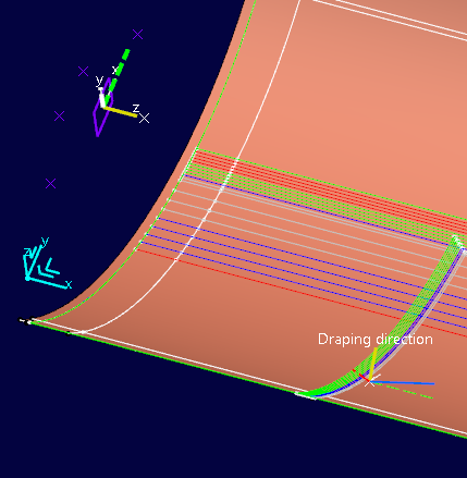
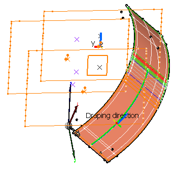
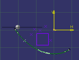
- Axes appear on the ply seed point on the surface, where:
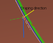
- The blue axis is the main fiber orientation of the ply.
- The red dotted axis forms a 90° angle with the main fiber orientation of the ply.
- The yellow axis is the draping direction of the ply (if the Transfer draping direction to plane normal check box is selected).
- If the main fiber orientation of the ply is different from 0°, the X-axis and Y-axis of the transferred rosette are shown too.
Optional: Clear the Only Consider cut-pieces check box.
When they exist, cut-pieces are created under a cut-piece group under the ply.
When Only Consider cut-pieces is selected:- If the ply has an associated cut-piece
group, the Flattening nodes are created under the
cut-piece group,
under the cut-pieces (one Flattening node per cut-piece). No Flattening node is created under the ply. - If the ply has no associated cut-piece group (thus no
associated cut-piece),
the Flattening node is created under the ply (one Flattening node per ply).
When Only Consider cut-pieces is cleared, Flattening nodes are created under all the plies
and all the cut-pieces (one flattening per ply and one per cut-piece).- If the ply has an associated cut-piece
group, the Flattening nodes are created under the
cut-piece group,
Select a plane as the flattening support.
- You can reference an existing plane under a plies
group.
As a consequence, the plane box is already filled when you launch the Flattening command and all created flatten curves lie on this plane. - Should you need to create the plane or the location point, right-click the appropriate box and create the element you need.
- Its name is displayed under Plane.
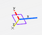
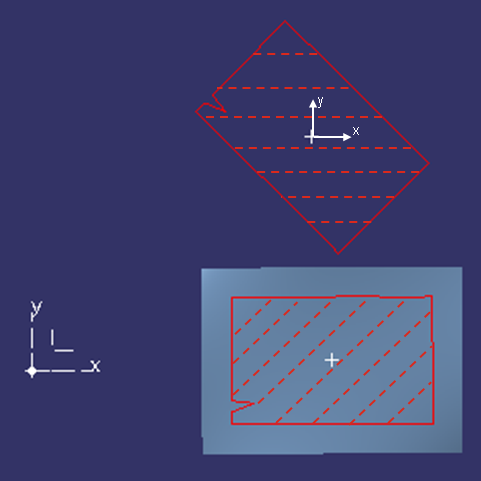
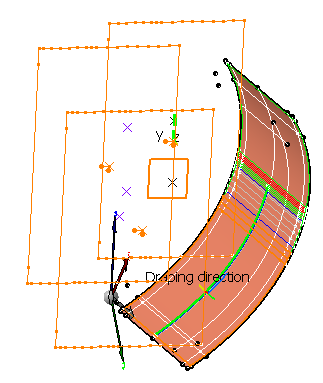
- Axes appear at the center of the plane or at the flatten
origin, where:
- The white axes are the X-Axis and Y-axis of the plane.
- The yellow axis is the normal (Z-axis) to the plane
that corresponds to the draping direction
(if the Transfer draping direction to plane normal check box is selected). - The blue axis is the 0° fiber direction of the flatten shape.
- The red dotted axis forms a 90° angle with the main fiber orientation (red axis) of the flatten shape.
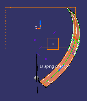
- The display varies with the flatten type:
With Material roll
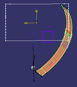
With Unfold assembly
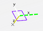
With Unfold assembly, the fiber direction is replaced by the rosette (green and white axes).
- You can reference an existing plane under a plies
group.
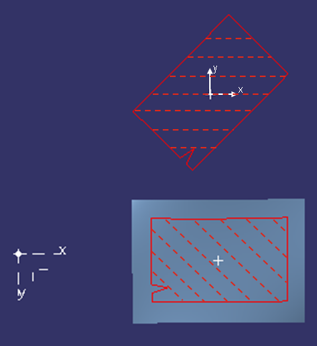
Optional: Select the Transfer draping direction to plane normal check box.
Selecting this check box: - Takes the hand of the
rosette into account:
- Example of a 45° ply with a right-handed rosette
- and with left-handed rosette
- Example of a 45° ply with a right-handed rosette
- Avoids upside/down errors when exporting the ply data.
- Make the understanding of the orientations of plies on the flatten plane easier.
The normal of the plane corresponds to the draping direction of the ply (yellow axes).
- Takes the hand of the
rosette into account:
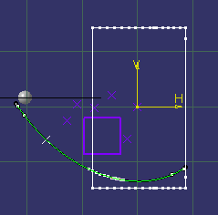
Select the location points doing one of the following:
- Pick one single point in the graphic area.
- Use the contextual menu of Location Point to create them.
- Select a geometrical set containing points.
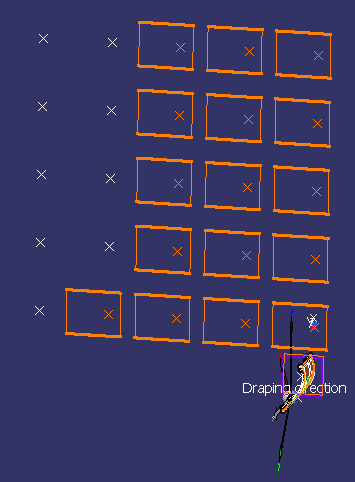
- Select a
pattern of points (e.g. RecPattern.3 under
Body.1 with Plane.2 as flattening plane).
This is a quick way to position the flattenings.
- Click
to select several points.
Each point or vertex (for patterns) is automatically assigned to a ply or a cut-piece.
If there are more plies or cut-pieces than points, the plies without location point use the center of the flatten plane as location point.
Check the selection of points with
that opens the Location Points dialog box.
The Points column is empty, then populated as you select points using any of the proposed methods.
Use the arrows in the dialog box to re-order points with respect to plies.Select a Flatten type and click Apply to visualize the flatten shapes.
-
Optional: Define a size for the flatten rosette.
This is useful when the size of the flatten geometry makes it difficult to visualize the rosette.
Optional: Select the Create Flatten as Sketch check box to associate the flatten curves to the plies.
- By default, Create Flatten as Sketch is
not selected.
The flatten curves of a given ply (contour and rosette) are created as a closed contour on the plane around
the location point, without any associativity with the ply.
- When Create Flatten as Sketch is selected:
- The flatten countour and rosette are projected onto the positioned sketches.
- For a given ply, two positioned sketches are
created.
One for the Rosette
One for the contour
They lie on the plane, their origin is the location point for producibility.
They are oriented along the X-axis of the rosette.
The positioned sketches are editable by double-click.
Edited positioned sketches are marked with an update icon.
Double-click the flattening node to re-run Flattening and update the Flattening result.
- By default, Create Flatten as Sketch is
not selected.
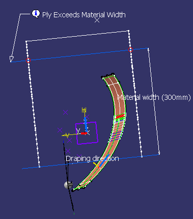
Optional: Select the Check material width check box and click Apply.
The check is done as follows:
- Two lines representing the material roll sides are displayed on the flatten shapes.
- The first line is positioned at the extremity of the flatten shape.
- If the second line intersects the flatten shape, a warning is displayed but does not prevent the creation of the flatten shape.
- If the flatten shape is larger than twice the material roll width, additional lines are displayed.
- With Along warp: The lines representing the material width are perpendicular to the blue line of the transferred rosette.
- With Along weft: The lines are perpendicular to the red line of the transferred rosette.
- Switching from one option to the other rotates the lines by 90°.
Diagnoses are displayed in the graphic area.
In addition, a red or green sign appears in the dialog box to indicate if the flatten shape fits into the material roll width (green mark) or not (red mark).
Select the type of smoothing continuity from the list:
- No Smoothing
- Threshold takes the tangency and curvature threshold into account.
- Point ensures no point discontinuity remains.
- Curvature ensures no curvature discontinuity remains.
Enter the required parameters Tangency threshold, Curvature threshold, Maximum deviation when available.
-
Select the Topology simplification check box, if required.
-
- A Flatten Body is created under each ply of
cut-piece, according to your choice. It contains the
following nodes:
- Outer Contours
- Inner Contours (A modification of the producibility can alter the order of the inner contours).
- Rosette
- Markers
- Cut
- No Category with the 3D elements transferred to 2D with possible smoothing, as Geometry Transfer.
- See Categorizing Flatten Body Elements for more information on categories.
- The flatten shape of the selected plies is generated using the producibility parameters (seed point, warp and weft) stored under each ply, as well as the seed orientation.
- Flatten curves (Flatten Rosette and
Flatten Contour) or sketches (Sketch.FlattenRosette
and Sketch.FlattenCurve) are created under
Flattening.
They lie on the support plane around the location point. - Each flatten curve or sketch corresponds to a ply or a
cut-piece.
The color code for their orientation is consistent with the one used when creating the plies. - An exclamation mark identifies the plies or cut-pieces exceeding the material width, if you have flattened them with the Check material width option.
- A Flatten Body is created under each ply of
cut-piece, according to your choice. It contains the
following nodes:
![]()