-
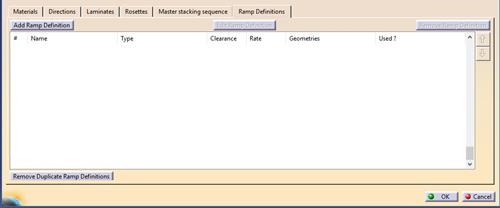
In Composites Parameters, click Add Ramp Definition.
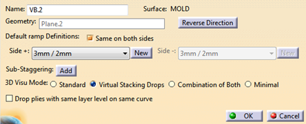
In Grid Panel, when editing a Reference elements group or a Reference element, click New under Default Ramp Definitions.
-
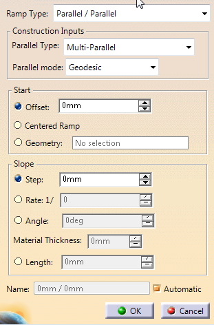
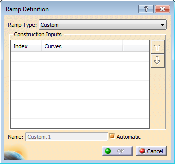
In the Ramp Definition dialog box that appears
-
- Select the Parallel Type from the list
Note that Chained parallels and Parallels from first result in several parallels computed in several steps.
They are more time consuming, and may be less accurate than the Multi-Parallel option. However, they ensure the compatibility of older designs.
They are also useful when you need a local control of the ramp support, or when the global computation does not meet your requirements.- Multi-Parallel: The parallels are build in one
single computation, as a Multi Parallel feature, from
the reference curve.
The computation is faster and safer. When this option is selected, the geometry creation and smoothing options are no longer available. - Chained parallels: Each parallel is computed after the previous one, by applying an offset and a deviation.
- Parallels from first: Each parallel is computed from the first one, by applying an offset and a deviation. /li>
- Multi-Parallel: The parallels are build in one
single computation, as a Multi Parallel feature, from
the reference curve.
- Select the Parallel Type from the list
-
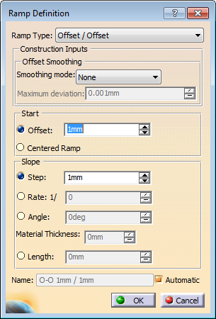
For Offset/Offset, select a Smoothing mode from the list and a Maximum Deviation if required.
-
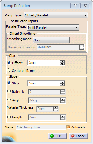
For Offset/Parallel , enter the parameters described in the previous two steps.
-
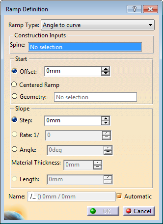
For Angle to curve, select a Spine, that is the curve with which the ramp forms an angle.
-
For the above types, do one of the following to define the Start (clearance).
- Enter an Offset.
-
Select a Geometry.
- If the clearance geometry is a point on the
surface, this reverts to applying an automatic offset.
The first curve of the ramp support goes through this point. - If the clearance geometry is a curve on the
surface, this curve becomes the reference of the first
curve of the ramp support.
As a consequence, the ramp support shape no longer depends on the geometry of the reference elements. - Likewise, if the clearance geometry is a plane or
a surface, the reference curve of the first curve of
the ramp support is the intersection
of the selected plane or surface with the reference surface.
- If the clearance geometry is a point on the
surface, this reverts to applying an automatic offset.
-
Select Centered ramp
support.
See More about Drop-off for more details. - Define the slope value either by a Step, a
Rate of the Material Thickness, an
Angle and Material Thickness or a
Length.
Material Thickness is given at Ramp Definition level.
-
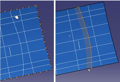
For Between two curves, select the top and the bottom ramp curves.
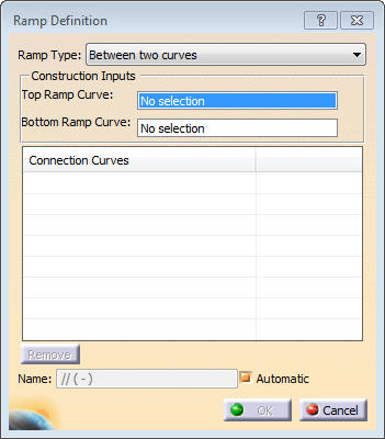
Click Add Connection Curves in the Ramp Definition table and specify them.
Connection curves provide a better control of the shape of the curves. -
For all types, define a Name, or select Automatic.
Automatic naming rules are as follows:
- Ramp Type: Since it is the most common type,
Parallel/Parallel has no suffix.
O-O stands for Offset/Offset,
O-P for Offset/Parallel,
/_ for Angle to curve,
I I for Between two curves,
Custom for Custom. - Parallel Type: Since it is the recommended type,
Multi-Parallel has no suffix.
CP stands for Chained Parallels,
FF for Parallel from First.
- Multi-Parallel:
35.56mm/3.5mm Centered/3.5mm (current centered)
Centered RS/3.5 mm (old centered)
Curve.1/3.5mm (geometric clearance)
35.56mm/1/20 (rate)
35.56mm/<125> (ramp length) - Other parallel types:
(CP) 35.56mm/3.5mm (Chained Parallels)
(FF) 35.56mm/3.5mm (Parallel from First) - Offset/Offset:
O-O 35.56mm/3.5mm - Offset/Parallel:
O-P 35.56mm/3.5mm
O-P (CP) 35.56mm/3.5mm
O-P (FF) 35.56mm/3.5mm - Angle to curve:
/_(Curve.1) 35.56mm/3.5mm - Between two curves:
I I (Curve.1-Curve.2) - Custom: Custom#1
- Ramp Type: Since it is the most common type,
Parallel/Parallel has no suffix.
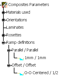
A Ramp
definitions node is created under Composites Parameters.
It contains the ramp
definitions, under nodes indicating their type.
For example:
Note: Ramp definitions created by cut angle commands are stored in a
dedicated node, also under Ramp definitions.