|
|
Thickness variations are needed to optimize Composites design. They are
achieved by dropping plies.
A drop-off can be defined by:
- A drop-off curve and a slope angle and a height.
- The drop-off curve is the reference curve driving the drop-off.
It must be parallel to the reference surface.
This curve is the top or the bottom of the ramp, if identified.
- The slope is the angle or drop-off ratio (e.g. 1:20) of the ramp with
respect to the reference surface.
- The height is the height of the bottom curve. This parameter is
associated with the slope to create the bottom curve.
- Or a drop-off curve and a bottom curve.
In this case, Slope and Height are not required.
- A ply border: if the top drop-off curve does not exist, you must identify a
ply border that will drive the drop-off.
As a consequence an offset of
(thickness at top – thickness at geometrical level x) is required as
input
as well as Slope and Height to compute the whole
ramp from top to bottom.
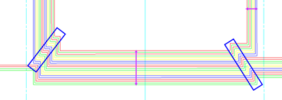
If necessary, you can modify the limits of the drop-off:
- Start/End limits of drop-off curve: allow an
extrapolation of the drop-off curve in order to generate a greater
surface
- Left/Right limits: allow to re-limit the ramp
surface in width and
to position it along its width
(particularly valued to a
tolerance to avoid gaps while intersecting the ramp with the context
surfaces)
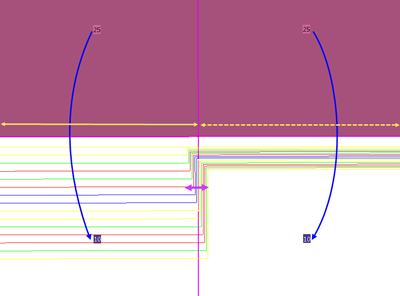
This option is proposed in Grid Panel when defining the staggering for structural reference elements or groups.
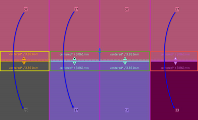
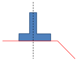
By default, the ply drop-off is placed after the structural element:
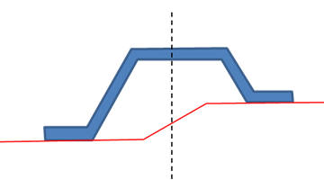
If you select Centered Ramp Support, the clearance distance of the corresponding ramp supports is automatically computed to center the ramp supports under the reference element.
It applies to all reference elements. The clearance distance is set as a formula using the number of ramp support curves and the step between those curves.
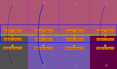
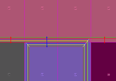
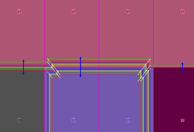
Centered Ply Drop (at Plies Generation)
This option is proposed in Grid Ramp Support and in Grid Panel when defining the staggering for structural reference elements or groups.
Centered Ply Drop (at Plies Generation) is another option proposed while defining the staggering.
When plies are generated, ramp supports are created for each sub-staggering definition.
|
|
|
Manage Drop-Off
The command Manage Drop-Off interactively changes
default plies drops with instant feedback on changes.
By default, ramp support curves are used from 1 to n: The first ply
uses the first curve, the second ply uses the second curves, and so on.
However, in some cases, mainly when the ply drop is driven by layer levels
(Master Stacking Sequence), you may need to override the drop-off order
(order in which the ramp support curves are used).
Another case is when you need to drop plies two by two. In this case,
you can reduce the number of generated curves by specifying that the first
curve is used by the first and second plies, the second curve is used by
the third and fourth plies, and so on.
Manage Drop-Off
- Not only changes the order of ramp support curves of the plies
contour, but also stores the related drop-off order information on the
corresponding ramp support.
The ramp support associated to the
first ramp curve selected for section identifies the ramp support drop
order to consider.
- Keeps the drop order in design at plies generation update: Any
drop order change is taken into account at the next plies generation.
- Consists in a local swap of edges in contour geometries and a
change on drop-off order on ramp support curves used in stacking.
- Interactive changes are kept (Master Stacking Sequence).
- As a consequence, drop-off changes are applied to plies using
curve of a same ramp support, associate to a single staggering
definition on reference element (default or sub-staggering).
|