-
Click Composites
Parameters  in the Parameters toolbar.
Go to the Rosettes tab.
-
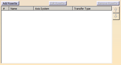
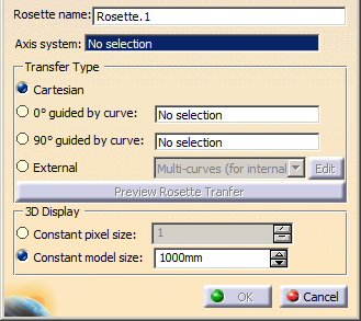
Click Add Rosette.
The Rosette Definition dialog box
appears
-
Optional: Edit the proposed name.
-
Select an Axis system.
A contextual menu is available to
create one.
-
Specify the Transfer Type.
See
About Rosette Transfer for more information.
-
For 0° guided by curve and 90° guided by curve, select the guide curve
(neutral fiber curve).
A contextual menu is available to create
one.
-
Click Preview Rosette Transfer.
See
Previewing the Rosette for more
information.
-
Specify the display size of the rosette.
Each rosette can have its
own display size.
- With Constant pixel size, the rosette display is
independent from the zoom. It has always the same size,
given in pixels.
- Wich Contant model size, the rosette display follows
the zoom, like any geometry.
|
-
Click OK to validate and revert to the Composites
Parameters dialog box.
The created rosettes are listed in the
dialog box, with their name, the name of the axis system they use and
the type of transfer.
They are created under Composites
Parameters, under the Rosettes node, as Rosette.X.
The
transfert type is aggregated under each rosette.
-
Select a rosette in the list and click Edit
Rosette to edit it, or
Remove Rosette to delete it.