- Accessing the Measure Between Dialog Box
- Defining Measure Types
- Defining Selection 1 and Selection 2 Modes
- Defining the Calculation Mode
Accessing the Measure Between Dialog Box
To access the Measure Between dialog box:
-
Click Measure Between
 .
In DMU, you can also select Analyze > Measure Between from the
menu bar.
.
In DMU, you can also select Analyze > Measure Between from the
menu bar.
The Measure Between dialog box is displayed: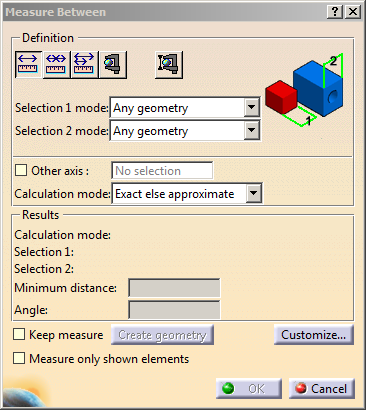

Notes:
-
When an object is selected in the 3D area, the last feature that modified the selected object is considered as the support feature for measure computation. This is illustrated in the following examples.
Example 1:
The selected face was last modified by Pocket.1 and not by Hole.1. Therefore, Pocket.1 is considered as the support feature for measure computation.
Example 2:
The selected face was last modified by Hole.1. Therefore, Hole.1 is considered as the support feature for measure computation. -
When the Measure selection is performed in the specification tree, the selected object for measuring is exactly the one from the tree. In the case of an Extract, selecting in the specification tree enables to perform measure computation on the Extract object itself.
Dialog Box Options
-
Other Axis: when selected, lets you measure distances and angles with respect to a local V5 axis system.
-
Keep Measure: when selected, lets you keep the current and subsequent measures as features.

This is useful if you want to keep the measures as annotations for example.
Some measures kept as features are associative and can be used to valuate parameters or in formulas.
Note that in the Drafting and Advanced Meshing Tools workbenches, measures are done on-the-fly and are therefore not persistent nor associative and cannot be used as parameters.
-
Measure only shown elements: when selected, lets you measure only the elements from the show space.
- Swapping the elements between show and hide spaces does not modify the existing measurements.
- An update (automatic or manual) of the existing measurements is necessary to modify them after the swap.
- Select this check box before selecting any elements.
-
Create Geometry: Lets you create the points and line corresponding to the minimum distance result. For more information, see Creating Geometry from Measure Results.
-
Customize... : lets you customize display of measure results. For more information, see Customize Measure Between.
-
Defining Measure Types
-
Between (default type): measures distance and, if applicable, angle between selected items.
-
Chain: lets you chain measures with the last selected item becoming the first selection in the next measure.
-
Fan: fixes the first selection as the reference so that you always measure from this item.
Defining Selection 1 and Selection 2 Modes
-
Any geometry: measures distances and, if applicable, angles between defined geometrical entities (points, edges, surfaces, etc.). By default, Any geometry option is selected.
The Arc center mode is activated in this selection mode.
This mode recognizes the axis of cylinders and lets you measure the distance between two cylinder axes for example. If you select the axis of cylinders in visualization mode or on a CGR representation, note the axis is still displayed after the measure is made. See pictures below:
 |
 |
Selecting an axis system in the specification tree
makes the distance measure from the axis system origin.
You can select sub-entities of V5 axis systems in the geometry area
only. For V4 axis systems, distances are always measured from the
origin.
- Any geometry, infinite: measures distances and, if applicable, angles between the infinite geometry (plane, line or curve) on which the selected geometrical entities lie. Curves are extended by tangency at curve ends.
Line |
Plane |
Curve |
 |
 |
 |
For an arc selection in Any geometry, infinite mode, this is the arc edge that is considered and no longer the arc center.
Any geometry, infinite |
Any geometry |
|
|
 |
Picking point: measures distances between points selected on tessellated geometries.
|
|
Notes:
|
In the DMU section viewer, selecting two picking points on a curve gives the distance along the curve between points (curve length or CL) as well as the minimum distance between points.
|
|
Notes:
|
-
Point only: measures distances between points. Dynamic highlighting is limited to points.
-
Edge only, Surface only: measures distances and, if applicable, angles between edges and surfaces respectively. Dynamic highlighting is limited to edges or surfaces and is thus simplified compared to the Any geometry mode. All types of edge are supported.
-
Product only: measures distances between products.
Products can be specified by selecting product geometry, for example an edge or surface, in the geometry area or the specification tree. -
Picking axis: measures distances and, if applicable, angles between an entity and an infinite line perpendicular to the screen. Simply click to create infinite line perpendicular to the screen.
|
|
Notes:
|
Intersection: measures distances
between points of intersection between two lines/curves/edges or a
line/curve/edge and a surface. In this case, two selections are
necessary to define selection 1 and selection 2 items.
Geometrical entities (planar
surfaces, lines and curves) are extended to infinity to determine the
point of intersection. Curves are extended by tangency at curve ends.
| Curve-plane | |
 |
|
| Line-plane | |
 |
|
| Curve-curve | |
 |
|
 |
|
|
|
Notes:
|
- Edge limits: measures distances between
start and end points of an edge. Only start and end points can be
selected with this option checked. The extremity nearest the selected
point is taken for the measurement.
- Arc center: measures distances between the
centers of arcs. To define arc center, click three points on
the geometry
Note: The resulting measure will always be approximate and non associative. -
Center of 3 points arc: measures distances between the centers of arcs defined by 3 points.
Note: This measure selection is not possible in Drafting and 2D related workbenches and the resulting measure will always be approximate.
-
Coordinate: measures distances between coordinates entered for selection 1 and/or selection 2 items.
Note: The resulting measure will always be non associative.
Defining the Calculation Mode
-
Exact else approximate (default mode): measures access exact data and wherever possible true values are given. If exact values cannot be measured, approximate values are given (identified by a ~ sign).
-
Exact: measures access exact data and true values are given.
|
|
Important:
|
-
In certain cases, in particular if products are selected, a warning dialog box informs you that the exact measure could not be made.
After some geometric operations, vertices (and corresponding macro points) may combine several representations on different supports (curves or surfaces). These representations are not all located in the same position in space which means that the exact position of the vertex cannot be determined. Only one vertex representation is visualized.
Measure Between measurements are made with respect to the visualized representation. Measuring distance between two points therefore depends on the chosen representation. Any calculation errors are due to the fact that the exact position of the vertex cannot be determined. -
Approximate: measures are made on tessellated objects and approximate values are given (identified by a ~ sign).
|
Notes:
If you checked the Keep Measure option in the Measure Between dialog box, your measures are kept as features and your specification tree will look something like this if measures were made on the active product.
Or like this, if measures were made on the active part.
Some measures kept as features are associative. In Design Mode, if you modify a part or move a part in a product structure context and the measure is impacted, it will be identified as not up-to-date in the specification tree. You can then update it locally have it updated automatically. When measures are used to valuate parameters, an associative link between the measure and parameter is created. Measures can also be used in formulas.
|