Stacking Management is started either from the Insert menu, the Analysis toolbar or another command.
- Does not support the creation of plies.
- Does not support the edition of single rows.
- Supports Undo/Redo only for sub-commands that modify the table,
e.g. move rows.
Undo/Redo work step by step.
-
Click Stacking Management
 from the Analysis toolbar.
Or click
from the dialog box of another command.
Or double-click a stacking in the specifications tree.The Stacking Management dialog box appears.
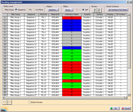
It aims at editing, selecting and reviewing a stacking. It is made of:- The table, i.e.
a 2D Viewer that can be panned and zoomed. Inside this
table:
- Information is given about the ply groups,
sequences, plies or cores, materials, orientations,
rosette, support surface and draping.
The background of the cells displaying the orientation has the same color as the orientation. - If you select a row in the table, it is highlighted in the graphic area.
- You can define the level of entities you are working
in (Plies Group, Sequence, Ply,
Cut Piece).
For each level, the number of rows of the table corresponds to the number of existing entities in the model. - You can filter entities, display information, and preview entities.
- Information is given about the ply groups,
sequences, plies or cores, materials, orientations,
rosette, support surface and draping.
- A set of tools gathered in the Tools Palette used to modify entities attributes or modifly the stacking.
- The table, i.e.
a 2D Viewer that can be panned and zoomed. Inside this
table:
-
Display the table according to your needs:
- Resize the dialog box to enlarge the 2D Viewer.
- Zoom in or out, or pan the table as you need, using standard commands.
This 2D Viewer displays Composites orientation cells with background colors that correspond to the ply orientation colors.
The color of the 2D Viewer cells change as you select or review entities:
- To review an entity, select a cell of the row containing
that entity, except the cell of the first column.
All the cells of the row are highlighted in green, except the first one that remains grey. - To select one or several entities, select the first cell of the corresponding rows.
The first cell of each row is highlighted in orange.
If you have selected one single row, all the other cells are highlighted in green.
If you have selected several rows, all the other cells of the last selected row are highlighted in green,
while those of the other rows are highlighted in orange.
The selection is kept when you click OK to exit the dialog box.
- Resize the dialog box to enlarge the 2D Viewer.
Select the Entity Level to display (Plies Group, Sequence, Ply or Cut Piece).
- Only the rows corresponding to the selected entity level are displayed in the 2D Viewer.
- Except for Cut Piece, the columns display the number of elements contained in the current level, its name if there is only one.
- For materials and rosettes, if all the elements of the level share the same attributes, this attribute is displayed. Otherwise, the number of attributes is displayed.
- For Plies Group, Sequence, Ply, if there are several orientations, drapings or core samples, Multi is displayed.
- If the geometries of two cut pieces are swapped (skin swapping), the surface of all the cut pieces is the result of the skin swapping (marked Invers_), while the plies that have cut pieces keep the initial surface.
- The manufacturing surface is managed at the Plies Group entity level.
For example, with the Entity Level set to Plies Group, the 2D Viewer looks like this:
Plies Group Sequence Ply/Core Material ID Orientation name Orientation Value Rosette Surface Draping 1 Plies Group.1 40 Sequences 40 Plies/1 Core 2 Materials Multi Multi Rosette.1 Extrude.1 FALSE
-
Filter rows from their attributes.
See Filtering Rows in the Stacking Management for more information. -
Adapt the display of information to your need.
See Displaying Information in the Stacking Management for more information -
Select the Entity Preview check box to start the previewer and check entities.
See Previewing Entities in the Stacking Management for more information. -
To review entities, do one of the following:
- Pick a cell in the 2D Viewer.
- Use the Review up and down arrows.
- Use the keyboard up and down arrows.
Entities are reviewed one by one.
The row you are reviewing is highlighted in green in the 2D viewer.
In the previewer, only the contour of the ply under review is highlighted. -
To add rows to a selection, do one of the following:
- Right-click a cell in the 2D Viewer and select Select/Deselect Row from Cell in the contextual menu to select it.
- Select a cell and clik Select Row from Cell from the Tools Palette.
- Pick the first cell on the left to select the whole row.
- Pick the (0,0) cell to empty the selection, or to select all the rows.
Multi-selection By Ctrl key is available.
The whole selection is highlighted in the specification tree.
In the work area, the plies of the selected plies group or sequence, or the contour of the selected ply or cut-piece are highlighted.
The selection is highlighted in blue in the 2D Viewer.
The last selected entity is considered as under review. -
Select Export Current Table
 in the Tools Palette and enter the storage path of
the file to create.
in the Tools Palette and enter the storage path of
the file to create.
The current table (made of the displayed columns) is exported. The file looks like this:
Plies Group Sequence Ply Cut Piece Material Direction Rosette Surface Draping 1 Plies Group.1 Sequence.1 Ply.1 SG452_G803 0 Axe-ref2 skin-ref1 false 2 Sequence.2 Ply.2 SG452_G803 0 Axe-ref2 skin-ref1 false 3 Sequence.3 Ply.3 SG452_G803 0 Axe-ref2 skin-ref1 false 4 Sequence.4 Ply.4 SG452_G803 0 Axe-ref2 skin-ref1 false 5 Sequence.5 Ply.5 SG452_G803 0 Axe-ref2 skin-ref1 false 6 Sequence.6 Ply.6 SG452_G803 0 Axe-ref2 skin-ref1 false 7 Plu.7 SG452_G803 0 Axe-ref2 skin-ref1 false 8 Ply.8 SG452_G803 0 Axe-ref2 skin-ref1 false 9 Sequence.9 Ply.9 SG452_G803 0 Axe-ref2 skin-ref1 false 10 Sequence.10 Ply.10 SG452_G803 0 Axe-ref2 skin-ref1 false 11 Sequence.11 Ply.11 SG452_G803 0 Axe-ref2 skin-ref1 false 12 Sequence.12 Ply.12 SG452_G803 0 Axe-ref2 skin-ref1 false 13 Ply.13 SG452_G803 60 Axe-ref2 skin-ref1 false 14 Ply.14 SG452_G803 0 Axe-ref2 skin-ref1 false 15 Sequence.15 Ply.15 SG452_G803 60 Axe-ref2 skin-ref1 false 16 Sequence.16 Ply.16 SG452_G803 0 Axe-ref2 skin-ref1 false 17 Ply.17 Ply.17Cut Piece.1 SG452_G803 0 Axe-ref2 skin-ref1 false 18 Ply.17/Cut Piece.2 SG452_G803 0 Axe-ref2 skin-ref1 false 19 Ply.17/Cut Piece.3 SG452_G803 0 Axe-ref2 skin-ref1 false -
Select entities in the 2D Viewer, and click OK to validate and exit the dialog box.
All the selected entities in a same level are stored and the selection is kept in the graphic area.
![]()