 Using the Interaction
Wizard
Using the Interaction
Wizard
Nonlinear Structural Analysis and Thermal Analysis include a powerful tool for identifying and creating common types of interactions between bodies in an assembled part or product. The interaction wizard simplifies the process of creating contact pairs and fastened pairs in a model. The wizard searches a model for geometric faces that lie within a specified separation distance, then creates either contact pairs (see Contact Pairs) or fastened pairs (see Creating Fastened Pairs) for every pair of detected faces; general analysis connections (see Creating General Analysis Connections) are also created automatically to act as supports for the contact pairs and fastened pairs. You can specify the areas of the model to search, the separation distance within which faces are likely to interact, the type of interaction that is created (contact pair or fastened pair), and the parameters assigned to each created interaction.
You can also use the interaction wizard to quickly review and modify any preexisting contact pairs and fastened pairs in a model.
Using the interaction wizard is a four-step process:
-
Define the search criteria that are used to locate interactions.
-
Specify default attributes that are used to define all located interactions.
-
Perform the search and review the located interactions.
-
Edit the attributes for individual interactions as necessary.
Each step in the process uses a unique dialog box. When you have completed the information in one dialog box, the next appropriate dialog box appears; you can also use the Back button to return to previous dialog boxes if necessary. Interactions are not added to the model while you are working in the interaction wizard. Once you are satisfied with the interactions defined in the wizard, click Finish to add them all simultaneously to the specification tree.
 Using the
Interaction Wizard: Creates contact pairs and
fastened pairs for all model faces within a specified distance
of each other.
Using the
Interaction Wizard: Creates contact pairs and
fastened pairs for all model faces within a specified distance
of each other.
The following topics cover the steps in using the interaction wizard:
-
Defining Default Interaction Parameters for the Interaction Wizard
-
Reviewing and Creating Interactions Using the Interaction Wizard
-
Editing Detected or Existing Interactions Using the Interaction Wizard
Defining Search Parameters
for the Interaction Wizard
When you click the Find Interactions icon , Nonlinear Structural
Analysis or Thermal Analysis opens the Step 1 dialog box
for the interaction wizard. In the first step of the
interaction wizard you indicate whether you are searching for
new interactions, reviewing existing interactions, or both
searching for new interactions and reviewing existing
interactions.
Before using the interaction wizard, you should set the current step in the active Analysis Case (see Analysis Cases). Newly detected contact pairs will be created in the current step and propagated to all subsequent steps. Newly detected fastened pairs will be created in the initial step (regardless of the current step) and are active through all steps in the analysis case. When reviewing existing interactions, the interaction wizard displays only those interactions that are active in the current step.
If you are searching for new interactions, you must provide some search criteria. These criteria include the search domain, the maximum distance between potentially interacting faces, and an option for extending surfaces in the created interactions.
When searching for new interactions, the interaction wizard considers only faces on different bodies in a model. You cannot use the interaction wizard to define self-contact or interactions between different faces on the same body. The interaction wizard uses the following specifications to define a body:
-
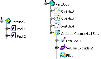
Multiple solid features (for example, two pad features) within the same part are not considered separate bodies, even if they are unconnected (see Figure 6–1).
-
Multiple surface or volume features (such as in a geometrical set) within the same part are considered separate bodies (see Figure 6–1).
-
Multiple part instances within an assembled product are considered separate bodies.
-
One-dimensional beam and wire geometries are not considered bodies.
Figure 6–1 The part on the left is considered a single body, regardless of the connectivity of the pad features; the part on the right is considered three separate bodies, regardless of the connectivity of the geometrical set features.
The interaction wizard searches for interactions between all bodies listed in the specification tree. If a body is generated from an existing body (for example, a volume feature is extruded from an existing surface feature or two existing volume features are joined to form a third volume feature), interactions may be detected involving both the original body and the generated body. To avoid creating excessive or duplicate interactions, the Include meshed geometry only option allows you to search only those bodies with a mesh assignment (this option is turned on by default); enabling this option typically eliminates from the search domain those bodies used as construction or reference geometry. The interaction wizard cannot detect interactions involving mesh objects without any underlying geometry.
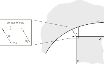
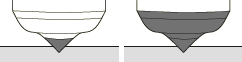
In addition, the interaction wizard uses some unmodifiable criteria during the search. In particular, two faces must be oriented toward each other. The interaction wizard compares the surface normals at the points of closest approach between two faces; if the two faces are offset by more than 45°, the interaction wizard will not create an interaction for these faces (see Figure 6–2).
Figure 6–2 Although Surfaces A and B are equidistant from Surface C, Surface A is oriented toward Surface C, while Surface B is not.
If two faces intersect each other, they must be oriented toward each other to be considered by the interaction wizard (see Figure 6–3).
Figure 6–3 An interaction is created between Surface A and Surface X, but an interaction is not created between Surface C and Surface X.
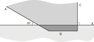
In Figure 6–3 one of the faces (Surface B) is completely enclosed within the other body. The interaction wizard considers separation distances on both sides of each face (interior and exterior) when searching for potential interactions. Therefore, this enclosed face is detected only if its depth of penetration is less than the specified separation distance criterion for the search. You can use the clash tool in the Assembly Design workbench to identify intersecting or enclosed faces that are not detected by the interaction wizard (see Detecting Clashes in the CATIA V5 Assembly Design User's Guide).
The interaction wizard also determines whether or not two faces are aligned with each other. For an interaction to be created between two faces, a surface normal from some point on one face must pass through the opposing face. For example, none of the faces in Figure 6–4 are considered aligned by the interaction wizard.
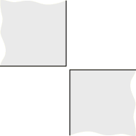
The surface extension option can be used to ensure that the surfaces in an interaction cover an appropriate area of the model. This option is controlled by an “extension angle.” All faces adjacent to each face in a detected interaction are also identified in the model. The minimum angle between the surface normals of the detected face and the adjacent face is measured along their common edge; if the angle is less than the specified extension angle, the adjacent face is included in the interaction. The surface extensions also propagate to faces adjacent to the updated surface. Figure 6–5 illustrates a situation in which surface extensions can be used to capture all of the faces on a contoured surface.
Figure 6–5 Surfaces created by the interaction wizard without surface extension (left) and with surface extension (right).
![]() This task shows you how to complete Step 1 of the
interaction wizard.
This task shows you how to complete Step 1 of the
interaction wizard.
-
If necessary, set the current step in the specification tree to the step in which new interactions should be created.
-
Click the Find Interactions icon
.The Find Interactions Wizard: Step 1 dialog box appears.
-
Specify whether you want to review existing interactions or search for new ones:
-
Choose Detect new interactions to search for potential interactions in the model.
-
Choose Manage existing interactions to use the interaction wizard to review and modify previously created contact pairs and fastened pairs that are active in the current step. Parameters for contact pairs can be modified only if the current step is the step in which the contact pair was created (with the exception of the connection behavior, which can be modified in any step). If you select this option, click Next to move directly to Step 3 of the interaction wizard (see Reviewing and Creating Interactions Using the Interaction Wizard); you can ignore the remainder of this procedure.
-
Choose Both to search for new interactions and review previously created interactions. After searching the model, the interaction wizard lists both newly detected and previously created interactions simultaneously.
-
-
Specify the search domain:
-
Choose Whole model to compare faces on every part in the model.
-
To search for interactions between specific parts in an assembled product, choose Select components and select the specific parts whose faces you want to compare. If you select a product from the specification tree, all part instances in that product are added to the search domain.
The Select components field is updated to reflect your selection.
-
-
By default, the interaction wizard searches only those geometric bodies that have a mesh assignment. This criterion prevents the creation of interactions involving construction or reference geometry. You should therefore assign a mesh to all bodies that are significant to your analysis before using the interaction wizard.
To search for interactions between all bodies in the specified search domain, regardless of their mesh assignments, toggle off Include meshed geometry only.
-
In the Detect interactions within tolerance field, enter the maximum distance between faces that are likely to interact. The interaction wizard can create interactions for any faces that are within this separation tolerance, provided they are aligned and oriented toward one another.
-
Toggle on Extend each surface by angle, and enter an appropriate extension angle to extend the interaction surfaces to include faces adjacent to those detected by the search.
-
Click Next to proceed to the next dialog box in the interaction wizard.
Defining Default
Interaction Parameters for the Interaction Wizard
When you have finished defining the search parameters (see Defining Search Parameters for the Interaction Wizard), Nonlinear Structural Analysis or Thermal Analysis opens the Step 2 dialog box for the interaction wizard. In the second step of the interaction wizard you specify the default parameters that are used to create interactions between faces detected by the search. If you opted to only manage existing interactions in Step 1, the Step 2 dialog box is skipped, and the interaction wizard proceeds directly to Step 3 (see Reviewing and Creating Interactions Using the Interaction Wizard).
The default parameters include the type of interaction (contact pair or fastened pair), the interaction behavior, the sliding formulation, surface adjustment settings, and formulation options. The specified default parameters are assigned to all newly detected interactions. However, you will have the opportunity to modify the parameters on individual interactions before adding them to the model.
![]() This task shows you how to create contact pairs for all
detected interactions. To create fastened pairs, see the task
immediately following this one. For more information about
contact pairs, see Contact Pairs.
This task shows you how to create contact pairs for all
detected interactions. To create fastened pairs, see the task
immediately following this one. For more information about
contact pairs, see Contact Pairs.
-
Select Contact as the Interaction Type.
-
Select a Mechanical or Thermal Connection Behavior from the specification tree.
The Interaction behavior field is updated to reflect your selection.
-
Specify the Sliding formulation:
-
Choose Finite sliding to allow for arbitrary separation, sliding, and rotation of the two surfaces.
-
Choose Small sliding if there will be relatively little sliding of one surface along the other. The small-sliding formulation is less expensive computationally than the finite-sliding formulation.
-
-
To automatically reposition slave nodes precisely onto the master surface during an analysis, toggle on Adjust slave nodes, and specify an adjustment option:
-
Choose Adjust overclosed nodes only to reposition only those slave nodes that are initially penetrating the master surface.
-
Choose Adjust nodes within, and enter a distance to reposition all slave nodes that initially lie within the specified distance from the master surface.
-
-
Specify the contact formulation:
-
Choose Surface to Surface to use the surface-to-surface contact formulation. Toggle on Include shell element thickness to account for the shell thickness when creating surface-to-surface interactions.
-
Choose Node to Surface to use the node-to-surface contact formulation.
-
-
Click Run to perform the interaction detection and to proceed to the next dialog box in the interaction wizard.
-
Before the next dialog box appears, a status bar indicates the progress of the interaction detection. If the progress is excessively slow, click Stop to abort the search and return to the Step 2 dialog box. You should modify the search parameters (see Defining Search Parameters for the Interaction Wizard) before performing the search again.
![]() This task shows you how to create fastened pairs for all
detected interactions. To create contact pairs, see the task
above. For more information about fastened pairs, see
Creating Fastened
Pairs.
This task shows you how to create fastened pairs for all
detected interactions. To create contact pairs, see the task
above. For more information about fastened pairs, see
Creating Fastened
Pairs.
-
Select Fastened as the Interaction Type.
-
To automatically reposition slave nodes precisely onto the master surface during an analysis, toggle on Adjust slave nodes.
-
Click Run to perform the interaction detection and to proceed to the next dialog box in the interaction wizard.
-
Before the next dialog box appears, a status bar indicates the progress of the interaction detection. If the progress is excessively slow, click Stop to abort the search and return to the Step 2 dialog box. You should modify the search parameters (see Defining Search Parameters for the Interaction Wizard) before performing the search again.
Reviewing and Creating
Interactions Using the Interaction Wizard
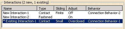
Once the search for interactions is complete, Nonlinear Structural Analysis or Thermal Analysis opens the Step 3 dialog box for the interaction wizard. This dialog box includes the Interactions table, which summarizes all of the interactions and the parameters assigned to them. The interactions that are listed depend on the settings you specified in the first step of the interaction wizard (see Defining Search Parameters for the Interaction Wizard): the Interactions table can list newly detected interaction candidates, existing interactions that are active in the current step, or both newly detected and existing interactions. Existing interactions appear in the Interactions table with an asterisk (*) in front of their name (see Figure 6–6).
When you click on a row in the Interactions table, the surfaces involved in the selected interaction are highlighted in the model. Master surfaces are highlighted in red; slave surfaces are highlighted in green. You can toggle off Highlight in viewport to disable surface highlighting. This option may be helpful if you are selecting a large number of interactions, since highlighting numerous surfaces may negatively impact display performance.
The items in the Interactions table represent the contact pairs and fastened pairs that will be added to the specification tree when you click Finish. Before adding these definitions, you can modify the parameters for individual interactions, delete interactions, or merge adjoining surfaces into a single interaction definition (merging is available only for newly detected interactions).
![]() This task shows you how to complete Step 3 of the
interaction wizard.
This task shows you how to complete Step 3 of the
interaction wizard.
-
If desired, disable the highlighting of slave and master surfaces on the model by toggling off Highlight in viewport.
-
You can control the visibility of model bodies using the Visibility Options:
-
Select Whole Model to display the entire model with the selected master and slave surfaces highlighted.
-
Select Master and Slave only to display only the parts that are connected to the selected master and slave surface; both the master and the slave surfaces are highlighted.
-
Select Master only to display only the part that is connected to the selected master surface; only the master surface is highlighted.
-
Select Slave only to display only the part that is connected to the selected slave surface; only the slave surface is highlighted.
-
-
To change the identifier for an interaction, click in the Name field and type a new name. This name will be used for the general analysis connection and contact pair or fastened pair when they are added to the specification tree.
-
To delete an interaction from the Interactions table, highlight the interaction row and click Delete. If you delete an existing interaction, the interaction wizard prompts you to specify whether or not the general analysis connection associated with the deleted contact pair or fastened pair should also be deleted. An existing contact pair can be deleted only if the current step is the step in which the contact pair was created.
-
To change an interaction's parameters, highlight the interaction row and click Edit. Nonlinear Structural Analysis or Thermal Analysis opens the Edit Interaction dialog box, which is discussed in Editing Detected or Existing Interactions Using the Interaction Wizard.
-
If two or more interactions involve surfaces that are joined at a common edge, you can merge them into a single interaction using the procedure below. To be merged, interactions must have identical parameters, and the adjoining surfaces must have common assignments (either both are master surfaces or both are slave surfaces). You cannot merge existing interactions.
-
Using [Ctrl]+Click or [Shift]+Click, select the interactions in the Interactions table that you want to merge.
-
If desired, you can merge only those interactions whose surfaces meet at an angle within a specified range. This angle is measured as the minimum offset between the two surface normals along the common edge. Toggle on Merge interactions within angle, and enter the desired angle.
-
Click Merge.
The highlighted interactions are replaced with a single entry in the Interactions table.
-
-
When you are satisfied with the contents of the Interactions table, click Finish.
Nonlinear Structural Analysis or Thermal Analysis creates a contact pair or a fastened pair for each entry in the table and adds it to the specification tree. If the Interactions table displays existing interactions, these interactions are updated with any changes you made in the interaction wizard.
Editing Detected or
Existing Interactions Using the Interaction Wizard
In the interaction wizard Step 3 dialog box (see Reviewing and Creating Interactions Using the Interaction Wizard), if you highlight an interaction (or multiple interactions) and click Edit, Nonlinear Structural Analysis or Thermal Analysis opens the Edit Interaction dialog box. The Edit Interaction dialog box allows you to modify the parameters for the highlighted interactions.
The Edit Interaction dialog box is similar to the Step 2 dialog box for the interaction wizard (see Defining Default Interaction Parameters for the Interaction Wizard); however, the parameters specified in the Edit Interaction dialog box apply to only the interactions that were highlighted in the Step 3 dialog box. You can change whether the interactions are contact pairs or fastened pairs and adjust the behavior, sliding formulation, and adjustment options associated with the interactions. If you are editing only a single interaction, you can also modify the interaction's name.
Most contact pair parameters can be modified only if the current step is the step in which the contact pair was created. The connection behavior for a contact pair can be modified in any step. Modifications to fastened pair parameters are always applied to the initial step, regardless of the current step.
![]() This task shows you how to modify the parameters for an
interaction using the Edit Interaction dialog box.
This task shows you how to modify the parameters for an
interaction using the Edit Interaction dialog box.
-
If you are editing a single interaction, you can change the interaction identifier by editing the Name field. This name will be used for the general analysis connection and contact pair or fastened pair when they are added to the specification tree.
-
The options for modifying the interaction parameters are identical to those used in the Step 2 dialog box for the interaction wizard. Refer to the procedures in Defining Default Interaction Parameters for the Interaction Wizard for instructions on using these options.
-
To reverse the master and slave surface assignments in the interactions, toggle Swap master and slave surfaces.
-
Click OK.
Nonlinear Structural Analysis or Thermal Analysis returns to the Step 3 dialog box for the interaction wizard and applies your changes to the Interactions table (see Reviewing and Creating Interactions Using the Interaction Wizard).