 Analysis Cases
A Finite Element Model can contain one or more analysis cases. An analysis case is a template (a set of objects sets) for defining environmental actions on a given system and the corresponding results. You can create a structural analysis case with the structural workbench in Nonlinear Structural Analysis or you can create a thermal analysis case with the thermal workbench in Thermal Analysis.
An analysis case consists of the following:
-
an Element Assignment object that defines the elements assigned to each mesh part
-
a Simulation History, containing a sequence of one or more steps, each of which may contain:
-
a Field Output Requests objects set (containing Field Output Request-type objects; not available in the Initialization step)
-
a History Output Requests objects set (containing History Output Request-type objects; not available in the Initialization step)
-
a Connections objects set (containing Connection-type objects)
-
a Loads objects set (containing Load-type objects; not available in the Initialization step)
-
a Boundary Conditions objects set (containing Boundary Condition-type objects; not available in the Initialization step)
-
a Fields objects set (containing Field-type objects)
-
-
a Jobs objects set that contains the jobs you create for the analysis case
-
optionally, one or more Masses objects sets that contain masses you create for the analysis case
-
a Display Groups objects set that contains the display groups you create for the analysis case
-
an Analysis Case Solution objects set that contains the results you request for the analysis; for example, images, reports, graphs, etc.
-
a Solution Sensors objects set that contains sensors added to record or parameterize field or history output results
![]() To create a Finite Element Model with an empty Analysis
Case:
To create a Finite Element Model with an empty Analysis
Case:
-
Select Start>Analysis & Simulation>Nonlinear Structural Analysis or Start>Analysis & Simulation>Thermal Analysis from the menu bar.
The New Analysis Case dialog box appears with the default analysis case selected (for example, Nonlinear Structural Analysis).
-
Select the desired case, and click OK in the New Analysis Case dialog box to enter the Nonlinear Structural Analysis or Thermal Analysis workbench.
 Warning: Do not select
Keep as
default starting analysis case in the
New Analysis
Case dialog box.
Warning: Do not select
Keep as
default starting analysis case in the
New Analysis
Case dialog box.An empty structural or thermal Analysis document is created.
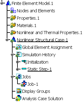
The Finite Element Model specification tree template displayed on the left side of the window (see Figure 4–1) shows the standard system representation object sets and an analysis case representation consisting of the following (empty) objects sets:-
Element Assignment
-
Simulation History, which includes the Initialization step and the default analysis step for the selected case
-
Jobs, which contains a default analysis job
-
Display Groups
-
Analysis Case Solution
-
To insert a new Analysis Case in a Finite Element Model:
Select Insert>Nonlinear Structural or Thermal Case from the menu bar.
The most recently created or edited analysis case is automatically set to be the current case; it is underlined in the specification tree. All analysis case operations you perform act on the current case; for example, when you insert an analysis step, it appears in the specification tree under the current case. To set a different analysis case to be current, right-click on the case in the specification tree and select Set As Current Case from the menu that appears.