Connection Properties
Connection properties are used to model the interaction between bodies in an assembled product. The following sections discuss the connection properties available in Nonlinear Structural Analysis and Thermal Analysis:
 Creating
Fastened Pair Properties: Fastens bodies together
at their common interface. Fastened pairs take into account the
elastic deformability of the interfaces.
Creating
Fastened Pair Properties: Fastens bodies together
at their common interface. Fastened pairs take into account the
elastic deformability of the interfaces.
 Creating
Bolt Tightening Connection Properties: Models
pre-tension in bolt-tightened assemblies.
Creating
Bolt Tightening Connection Properties: Models
pre-tension in bolt-tightened assemblies.
 Creating
Pressure Fitting Connection Properties: Prevents
bodies from penetrating each other at a common interface where
there are interferences or overlaps between the bodies.
Creating
Pressure Fitting Connection Properties: Prevents
bodies from penetrating each other at a common interface where
there are interferences or overlaps between the bodies.
 Creating Fastened Pairs
A fastened pair is the link between two part bodies that are tied together at their common boundary and behave as if they were a single body. From a finite element model point of view, this is equivalent to the situation where the corresponding nodes of two compatible meshes are merged together. However, since part bodies can be meshed independently, fastened pairs are designed to handle incompatible meshes.
Fastened pairs take into account the elastic deformability of the interfaces.
You can use a general analysis connection or a Contact or Coincidence assembly constraint to define the surfaces that are interacting. For more information, see Specifying Contact Surfaces. Table 6–2 summarizes the constraints and connections that can be used to define a fastened pair in Nonlinear Structural Analysis and Thermal Analysis.
| Assembly Design Workbench | Nonlinear Structural Analysis and Thermal Analysis | |
|---|---|---|
| Coincidence Constraint | Contact Constraint | General Analysis Connection |
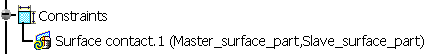
The order in which the two surfaces are specified when the constraint or connection is defined is critical because of the manner in which their interaction is discretized. The first surface selected is considered the “master” surface, and the second surface selected is considered the “slave” surface. When a constraint is added to the specification tree, the surfaces are listed in this order, as shown in Figure 6–7.
Figure 6–7 The specification tree entry for a Contact assembly constraint, showing the master and slave surfaces.
For each node on the “slave” surface the solver attempts to find the closest point on the “master” surface of the contact pair where the master surface's normal passes through the node on the slave surface. The fastened pair is then discretized between the point on the master surface and the slave node.
A fastened pair does not necessarily fasten the entire selected slave surface to the master surface. Instead, Nonlinear Structural Analysis and Thermal Analysis use a position tolerance, or distance from the master surface, to determine which nodes on the slave surface should be fastened to the master surface; any slave nodes outside of this tolerance in the initial model configuration are not included in the fastened pair. The solver calculates a default position tolerance based on a number of factors in the model. This default tolerance is typically suitable for fastening two proximate surfaces, but you can redefine the position tolerance if necessary.
If you need to create multiple fastened pairs in a model, you should consider using the interaction wizard. The interaction wizard automates many of the steps involved in defining fastened pairs and can create multiple fastened pairs simultaneously. See Using the Interaction Wizard for more information.
![]() This task shows you how to create a fastened pair between
two parts.
This task shows you how to create a fastened pair between
two parts.
-
Click the Fastened Pair Property icon
.The Fastened Pair dialog box appears, and a Fastened Pair object appears in the specification tree under the Properties objects set.
-
You can change the identifier of the fastened pair by editing the Name field.
-
In the specification tree, select a general analysis connection or a Contact or Coincidence assembly positioning constraint to apply to the fastened pair.
The Supports field is updated to reflect your selection. The first surface specified in the connection or constraint is used as the master surface in the contact pair; the second surface is used as the slave surface.
-
Optionally, if either or both of the surfaces involved in the fastened pair are shells, click Flip Master and/or Flip Slave to reverse the direction of the surface normals.
-
To reverse the order of the master and slave surfaces in the fastened pair definition, toggle on Swap master and slave surfaces.
The red highlighting and arrows indicating the master surface replace the green highlighting and arrows indicating the slave surface, and vice versa.
-
To help you view the configuration of the master and slave surfaces in a complex model, you can use the Visibility Options to view only the part containing the master surface or only the part containing the slave surface.
-
Select the appropriate Position Tolerance for the fastened pair:
-
Choose Use computed default to use the position tolerance that is calculated automatically by the solver.
-
To define the position tolerance directly, choose Specify distance, and enter a position tolerance.
If you define the position tolerance directly, you can preview which slave nodes are included in the fastened pair by clicking Highlight nodes; Nonlinear Structural Analysis or Thermal Analysis highlights those nodes on the slave surface that lie within the specified position tolerance from the master surface. Both surfaces involved in the fastened pair must be meshed to preview the fastened nodes. The previewed nodes are approximations only; the nodes indicated in the preview display may be slightly different than the nodes that are fastened during the analysis. However, the preview should identify general regions of interest in the model when configuring a fastened pair.
-
-
By default, the solver moves all slave nodes in a fastened pair directly onto the master surface at the beginning of an analysis. This adjustment does not create strains in the model and typically improves performance. To allow initial gaps between the fastened surfaces to remain during the analysis, toggle off Adjust slave node initial position.
-
Select the Formulation option for the fastened pair:
-
Select Solver Default to use the best formulation as determined by the solver.
-
Select Node to Surface to use the node-to-surface formulation.
-
Select Surface to Surface to use the surface-to-surface formulation.
-
-
If you are not using the Solver Default formulation, you can ignore the thickness associated with shell elements in the fastened pair by toggling off Include shell element thickness.
-
Click OK in the Fastened Pair dialog box.
A symbol representing the fastened pair appears on the corresponding faces.
Creating Bolt Tightening
Connection Properties
A bolt tightening connection property takes into account pre-tension in bolt-tightened assemblies. The computation is carried out according to a two-step approach. In the first general static step of the analysis the model is submitted to tension forces due to bolt tightening by applying opposite forces on the bolt thread and on the support tapping, respectively. In general, the first step in your simulation history will not contain other loads, so the bolt tightening connection property can be evaluated and used as a precondition for the rest of the analysis. Then in the second step of the analysis the relative displacement of the two bolt surfaces (obtained in the first step) is fixed while further loading is applied to the model. Since bodies can be meshed independently, bolt tightening connection properties are designed to handle incompatible meshes.
Bolt tightening connection properties account for the elastic deformability of the interfaces.
A bolt tightening connection property is defined in terms of the two surfaces that may interact. These surfaces are indicated through the definition of an assembly constraint or an analysis connection. You can use an assembly constraint defined in the Assembly Design workbench to define the contact surface pairing between the bolt thread and the bolt support tapping. Alternatively, you can use a general analysis connection to define the contact surface pairing. Table 6–3 summarizes the constraints that can be used to define a bolt tightening connection property.
Table 6–3 Bolt tightening connection properties.
| Assembly Design Workbench | Nonlinear Structural Analysis | |
|---|---|---|
| Coincidence Constraint | Contact Constraint | General Analysis Connection |
You can request history output of relative displacements and rotations and of total, elastic, viscous, and reaction forces and moments from a bolt tightening connection property. The support for the history output request is the connection mesh.
![]() This task shows you how to create a bolt tightening
connection property between two parts.
This task shows you how to create a bolt tightening
connection property between two parts.
-
Click the Bolt Tightening Connection Property icon
.The Bolt Tightening Connection Property dialog box appears. A symbol representing the bolt tightening connection property appears on the corresponding faces, and a Bolt Tightening Connection Property object appears in the specification tree under the Properties objects set.
-
You can change the identifier of the bolt tightening connection property by editing the Name field.
-
In the specification tree, select an assembly constraint created previously in the Assembly Design workbench or a general analysis connection created previously in Nonlinear Structural Analysis.
The Supports field is updated to reflect your selection.
-
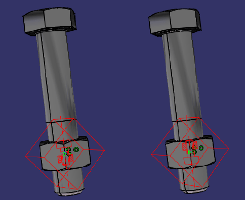
If necessary, modify the default values of the force and orientation parameters. Choose either the same or the opposite orientation so that the graphic representation of the bolt tightening connection property matches the bolt direction (see Figure 6–8). A positive force represents tightening.
Note: In some cases when the centers of the bolt and nut supports are aligned exactly, the graphic representation of the bolt may not be oriented properly. As a result, the bolt force may not be applied as intended. Nonlinear Structural Analysis will issue a warning message to inform you of these situations when you submit the simulation for analysis.
-
Click OK in the Bolt Tightening Connection Property dialog box.
Creating Pressure Fitting
Connection Properties
A pressure fitting connection property is the link between two part bodies that are assembled in a press-fit configuration. Two common approaches are used to model the initial press fit: gradual resolution of an initial interference or gradual forcing apart of initial contact to open a gap. In both cases large contact pressure results between the parts. Pressure fitting connection properties take into account the elastic and plastic deformability of the material.
Since part bodies can be meshed independently, pressure fitting connection properties are designed to handle incompatible meshes.
You can use a general analysis connection or a Contact or Coincidence assembly constraint to define the surfaces that are interacting. For more information, see Specifying Contact Surfaces. You cannot create a pressure fitting connection property between surfaces of two-dimensional surface parts. Table 6–4 summarizes the constraints and connections that can be used to define a pressure fitting connection in Nonlinear Structural Analysis.
Table 6–4 Pressure fitting connection properties.
| Assembly Design Workbench | Nonlinear Structural Analysis | |
|---|---|---|
| Coincidence Constraint | Contact Constraint | General Analysis Connection |
For each node on the “slave” surface the solver attempts to find the closest point on the “master” surface of the contact pair where the master surface's normal passes through the node on the slave surface. This normal is considered the contact direction.
![]() This task shows you how to create a pressure fitting
connection property between two parts.
This task shows you how to create a pressure fitting
connection property between two parts.
-
Click the Pressure Fitting Connection Property icon
.The Pressure Fitting Connection Property dialog box appears, a Pressure Fitting Connection Property object appears in the specification tree under the Properties objects set, and a Pressure Fitting Connection Mesh object appears in the specification tree under the Nodes and Elements objects set.
-
You can change the identifier of the pressure fitting connection property by editing the Name field.
-
In the specification tree, select a general analysis connection or a Contact or Coincidence assembly positioning constraint to apply to the pressure fitting connection property.
The Supports field is updated to reflect your selection. The first surface specified in the connection or constraint is used as the master surface in the contact pair; the second surface is used as the slave surface.
-
Enter a value for the minimum normal clearance in the Overlap field.
-
Use a positive overlap value when the surfaces are initially in contact. The surfaces are pressed apart gradually over the time period of the step to reach this overlap value.
-
Use a zero overlap value when the surfaces are initially overclosed. Automatic shrink fit contact interference is used to resolve the overclosure gradually over the time period of the step.
-
A negative overlap value is not allowed.
The coordinates of overclosed nodes are adjusted in the output database; however, these coordinates are not adjusted in CATIA V5. Therefore, when you view the results of the analysis, the displacements are applied to the original coordinates rather than the adjusted ones.
-
-
Click OK in the Pressure Fitting Connection Property dialog box.
A symbol representing the pressure fitting connection property appears on the corresponding faces.