|
This command is only available with the
Automotive Body in White Templates product. |
 |
This task shows you how to create 2D-view section which is a set
used as a means to visualize geometry details along multiple section
planes and that can contain all types of GSD features. It allows you to:
- generate GSD wireframe planar objects from the intersection of a
3D geometry with an intersection plane,
- represent these objects in a view plane which may be different
from the intersection plane,
- use the tools from the Sketcher workbench to create additional
2D sketcher wireframe objects in the view plane,
- transfer geometries created in the Sketcher workbench in both
view plane and intersection plane,
- easily apply corner and thickness operations to GSD geometries
in the view plane,
- visualize and select filters associated to geometries generated
in the sections context.
|
| |
This task also deals with:
|
 |
Open the
2DViewSection1.CATPart document.
|
 |
-
Click Insert 2D-View Section
 in the Sections Management
toolbar. in the Sections Management
toolbar.
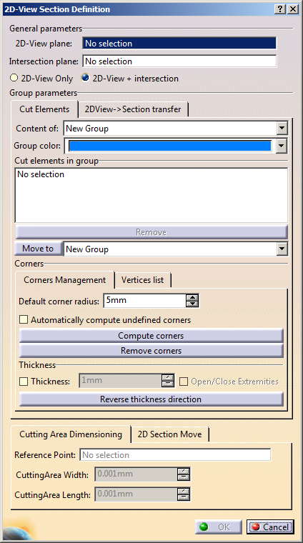
The 2D-View Section Definition
dialog box appears.
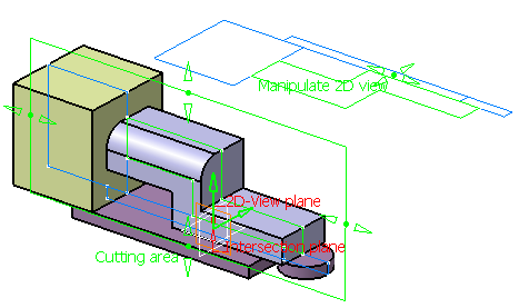
-
In the 2D-View plane
box, select the
visualization plane or planar surface.
Here we selected the xy plane.
-
In the Intersection plane
box, select the
cutting plane or planar surface.
Note: Both planes may be identical, parallel or unrelated. You can
create a 2D-view section with only these two inputs, however the created
2D view section will be very similar to a geometrical set or ordered
geometrical set.
Here we selected the zx plane.
-
Select whether you want to show only the 2D view
(2D-View
only) or the 2D view and the 3D intersections
(2D-View +
intersection) in both view and intersection planes.
Here we selected 2D-View + intersection.
-
In the Content of list, select where you want
to put the selected geometrical elements: either to a new group if none
exists already (as in our scenario) or an existing group (Group.x).
-
In the Group Color list, select the color of
wireframe objects for the current group.
By default, the blue color is used.
 |
The geometries selected in the Cut elements in group area
may be gathered in different groups. Every group
has its own
color to distinguish the generated wireframe objects created by
intersecting geometries of every group with the intersection
plane. Intersection and visualization planes must be common to all
the groups.
|
-
In the Cut elements in group area, select the
geometrical elements of your choices (curves, surfaces, volumes or
solids) to be inserted in the current group.
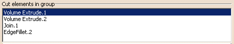
Note: You can select the element and click
Remove to delete it from the
list.
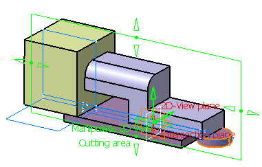
A rectangular boundary appears on the plane chosen as the cutting plane
along with manipulators.
|
|
The result of the section of the selected geometrical
elements with the section plane may be a set of
non-connex wireframe elements. A warning message appears each
time a modification of the intersected
geometry set results in a non-connex set of intersection
wireframe elements. |
-
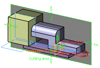
Modify the size of this rectangle using the
manipulators.
The rectangle area is frozen, i.e. automatic dimensioning does not work
anymore when adding or removing
elements from the intersected geometries.
-
Right-click any of the manipulators of the cutting plane
and select the Reset to default position command.
The delimiting rectangle is reset to its initial position and the
intersecting element is the bounded cutting surface originally selected.
 |
This contextual menu is only available after one of the
manipulators has been moved. |
-
From the Cutting Area Dimensioning tab,
select a point in the Reference Point box and define width
and height to specify the dimensions of cutting area.
Note: If the
reference point lies outside the cutting plane, then it is projected on
the cutting plane.
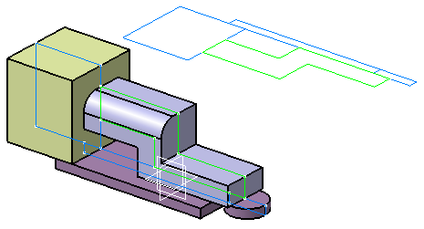
-
Select EdgeFillet.2
in the Cut elements in
group, select New Group
among the possible destinations
from the combo list and click Move to.
-
In the Group Color list, select another color
for this new group.
Here, we selected the green color.
-
Use the 2D view manipulators to move the 2D-view section
for a better visibility.
|
|
- Click Display only Selected Elements to
temporarily hide all elements from the 3D area except
selected ones,
until the view is restored by deactivating the view filter.
- Click Set Pickable only Selected Elements to
temporarily see all elements as unpickable in the 3D area
except selected ones, until the pickable mode is restored by
deactivating the selection filter.
|
-
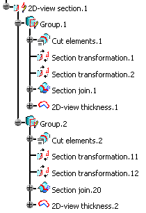
Click OK to create the 2D-view section.
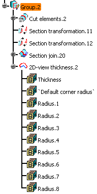
It is created in the current In Work Object. Grouping intersected
geometries also has an influence on the structure of specification tree
under the 2D-view section feature. Every group generates a node in the
specification tree directly under the 2D-view section feature:
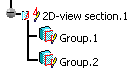
-
Click
Filter the Section's components
 to hide
all the nodes of the specification tree under the Group node:
to hide
all the nodes of the specification tree under the Group node:
|
|
|
Compute Corners and Thicknesses
|
|
|
You can compute corners and thickness to the 2D-view section.
The elements of the Section join node in the specification tree can be
automatically used as an input to a corner and/or a thickness operation.
These options are activated and parameterized from the 2D-view section
command dialog box. They are activated or deactivated independently for
every group contained in the 2D-view section feature container. |
|
|
-
Double-click the 2D-View Section
in the specification tree to edit it.
The 2D-View Section Definition dialog box appears.
-
Select the 2D-View only
option.
-
Select Group.2 containing
EdgeFillet.2.
-
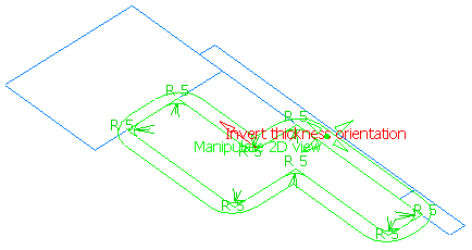
In the Default corner radius
box, enter the
corner radius value.
By default, the value is 5mm.
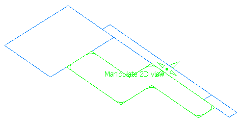
-
Click Compute corners to manually apply the
corner operation on the sharp vertices contained in the Section join
node.
The default corner radius defined in the dialog box is used for all
created corners. You can independently modify each corner radius by
double-clicking the radius value in the 3D area and set a different
value.
|
|
- When a corner generated using Compute corners
is absorbed by another corner operation, the 3D display
remains, allowing you to manually modify it.
- A corner value of 0 preserves the sharp edge as it is.
- Click Remove corners to remove the corners
which are generated by Compute corners.
- If you change the corner radius value, corners must
first be removed to be recomputed with the modified
value.
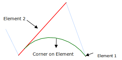
- If the corner on vertex is not available, corner on
elements will be created. Specifications for corner on
element on any particular sharp vertex to be cornerized will
be as follows:
- If none of its adjacent sharp vertices are
already cornerized: Distance between the vertex
to be cornerized and the adjacent sharp vertices
on both sides are computed. The vertex with
minimum distance from vertex to be cornerized is
taken as Element 1 and the edge on the other
side of vertex to be cornerized is taken as
Element 2.
- If one of the adjacent sharp vertices is
already cornerized: The adjacent sharp vertex is
taken as Element 1 and the adjacent Edge+Corner
is taken as Element 2.
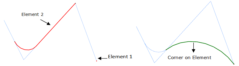
- If no solution with these inputs, C0
solution will be computed. The adjacent non
sharp vertex is taken as Element 1 and the edge
between current vertex and adjacent sharp vertex
is taken as element 2.
- If both the adjacent sharp vertices are
already cornerized: Distance between the vertex
to be cornerized and the end vertices of corners
on adjacent sides are computed. The Edge+Corner
on the side of farther vertex is taken as
Element 2. The Vertex between the adjacent Edge
and corner, on the nearer side is taken as
Element 1.
|
|
-
Select the Automatically compute undefined corners
check box to apply a new corner operation on undetermined vertices which
may remain after the compute corners operation.
Undetermined vertices are sharp vertices introduced after being created
using Compute corners.
|
|
This check box does not affect sharp edges which result from
setting their radius to 0 during the corner computation. |
When this option is used without having created the corners with Compute
corners, it systematically applies the default corner radius on all
sharp vertices:
-
Select the Thickness check box and enter a
value to compute the thickness.
The default value for the thickness is 1mm. Here we selected 5mm.
This option can be applied on the result of a corner operation or on the
elements of the Section join group if no corner operation has been
defined. It is composed of a parallel curve followed by a closing lines
operation.
|
|
The closing lines operation is performed when the
characteristics of the body representing a 2D-view thickness
feature match with the characteristics of the body representing
a section join feature. For example, the closing line operation
is possible when the number of domains in input body and output
body are same. |
|
|
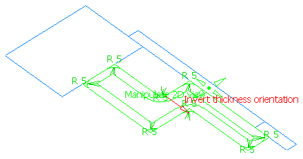
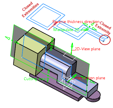
You can click the Invert thickness orientation
button in the dialog box or the red arrow in the 3D area to
inverse the orientation of the parallel curve:
 |
|
|
The thickness and corner operations use the visualization
plane (or planar surface) as the support. In the
case of a bounded planar surface used as visualization plane, it
is necessary that all elements on which the
corner and thickness operations are performed lie within the
visualization planar surface. If this is not the
case, a warning message is issued and the operation fails.
|
-
Optionally, you can
select the Ope/Close Extremitnies check box to open the thickness at either extremities.
|
|
- If you have cleared the Thickness
check box, the Open/Close Extremities
check box remains disabled.
- By default, the Open/Close Extremities
check box is cleared.
|
|
|
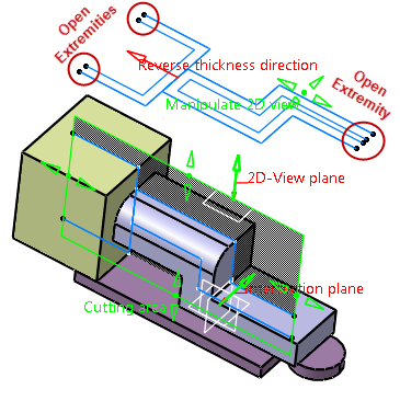
Depending on the position of the cutting area with
respect to the cutting element, the command gives
following results:
- Cutting area lies inside the limits of
the cutting element:
| a. If the Open/Close Extremities check box
is selected |
b. If the Open/Close Extremities check box
is cleared |
 |
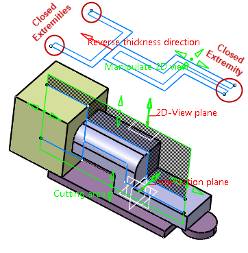 |
| Result: Thickness at both the
extremities is open. |
Result: Thickness at both the
extremities is closed. |
| |
|
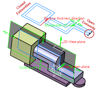
- Cutting area lies outside the limits of
the cutting element:
| a. If the
Open/Close
Extremities check box is selected |
b. If the Open/Close Extremities check box
is cleared |
 |
 |
| Result: Thickness
at the right extremity is open,
while at the left it is closed, due
to cutting area exceeding the
cutting element. |
Result: Thickness at both the
extremities is closed. |
|
|
|
-
Optionally, click the Vertices list tab.
The Vertices list tab displays all the
vertices at the sharp corners of the 2D-view section.
The vertices are sorted as follows:
- If the curve contains only convex or concave corners,
the vertices are sorted in descending order of their radii.
- If the curve contains convex and concave corners or
sections with consecutive convex or concave corners, all
vertices of the convex corners are listed first followed by
the vertices of all concave corners unless Thickness
option
is used.
If Thickness is defined and the direction is reversed using
Reverse thickness direction, the convex - concave
order is reversed, that is in this case the vertices of
concave corners are computed first.
By default, all consecutive vertices of the same type are
listed in descending order of their radii. However, this is
no longer valid if the order is changed manually using the
Move up or Move down button.
Note: The list is updated dynamically when changing a radius
provided that the vertices order was not modified using a
manipulator in 3D or the Move Up and Move Down
buttons in the dialog box.
|
-
Optionally, you can change the order in which the
corners are computed by reordering the vertices. Select a vertex and
click Move Up or
Move Down to reorder the list.
The vertex is highlighted in the 3D geometry area.
|
|
The Vertices list tab displays the list of
vertices in either of the following cases:
|
|
|
-
In case of overlapping corners between two vertices, you
can also swap the computation order of
the corners concerned using the handle appearing in the work
area between the corresponding vertices. In the
Vertices list, the order will be updated
automatically.
- If the locally changed order impacts the computation
order of these vertices with adjacent overlapping vertices,
the computation order of other overlapping vertices will be
swapped until they
match the arrow directions of existing handles.
|
-
Click OK to apply the corner and thickness
operations to the 2D view section.
The 2D-view thickness node in the specification tree contains the result
of the corner and thickness operations.
|
|
|
Edit 2D-View Sections
|
|
|
You can edit 2D-view sections. It is possible to use the tools from the
Sketcher workbench to create additional wireframe elements in the
2D-view section feature.
There are two different ways to do so:
- Use the contextual command on the 2D-view section to create a
temporary sketch under the 2D-view section then
all the section's group
in the specification tree.
- Use the contextual command on the 2D-view section group to create a
temporary sketch under the specific group, just before the Section join
node. This means that wireframe elements created in the group will be
used for further corner and thickness operations. This is not the case
for elements created directly under the 2D-view section feature.
|
|
|
-
Right-click the 2D-View Section.1
in the
specification tree and select the 2D view section.1 object > Edit
Section command.
The Sketcher workbench opens.
-
Create a rectangle for instance.
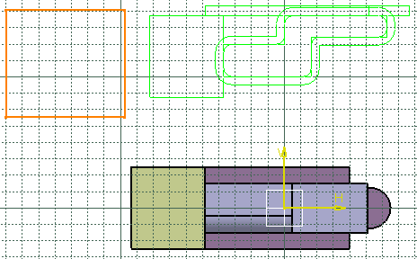
-
Click to exit the Sketcher workbench.
The curve appears in the 3D area and added to the specification tree:
Once you have created a sketch containing no constraints and exited the
Sketcher workbench, elements of this sketch are transferred to
equivalent GSD wireframe features and the sketch is deleted. The
generated features replace the temporary sketch in the specification
tree.
|
|
If the created sketch contains constraints, a warning
message appears when exiting the Sketcher workbench. You have
two choices:
- If the constraints can be lost, sketcher elements are
converted into GSD features as described above.
- If the constraints must be kept, sketcher elements are
not replaced by GSD features and the sketch remains at its
place in the specification tree when exiting the Sketcher
workbench.
|
|
|
|
Edit 2D-View Section Parameters
|
|
|
You can edit the parameters of the wireframe elements
aggregated under the 2D-view section node. |
|
|
-
Right-click the 2D-View Section.1
in the
specification tree and select the 2D view section.1 object > Edit
Parameters.
The parameters of the element are displayed.
-
Double-click any value in the 3D area.
The Parameters dialog box appears.
-
In the Value box, enter a value or use the arrows to
change the value.
-
Click OK.
-
Select Edit > Update to update the new parameter.
The new parameter is applied.
|
|
To display parameters permanently, select the Parameters of features and
constraints check box from
Tools > Options > Infrastructure > Part
Infrastructure > Display area. |
|
|
|
Transfer Elements from the View Plane to the Section Plane
|
|
|
Once a section is edited as described above and new wireframe elements have
been created, these elements are contained in the view plane and may be
transferred back to the section plane.
This is true for elements created under a 2D-view section group or
directly under the 2D-view section, whether wireframe or non-wireframe,
within the view plane or not and for elements contained within a sketch
or GSD features extracted from a sketch as described above.
The transfer may generate elements out of the section plane, however
every element contained in the view plane will generate an element in
the section plane.
|
|
|
-
Double-click the 2D-view section in the specification
tree to edit it.
The 2D-View Section Definition dialog box appears.
-
Select the 2DView > Section transfer tab.
The elements than can be transferred are displayed in the right-column
list:
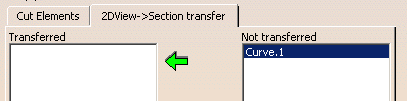
This list contains all the features contained in the 2D-view section
node in the specification tree (GSD or sketcher, within groups or not,
wireframe or not, contained in view plane or not).
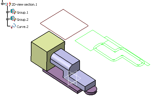
-
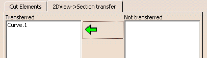
Choose the element to transfer (here Curve.1)
from the right-column list and click the green arrow.
It is transferred to the left-column list: In the Value box, enter a
value or use the arrows to change the value.
|
|
- You can also choose the element to transfer by selecting
the element from 3D geometry. If element is in right-column
list then it is transferred to the left-column list and
vice-versa.
- The elements created by editing the section group are
identified with an asterisk and are strictly contained in
the view plane.
|
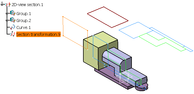
-
Select the group where to transfer the elements in the
list.
-
Click OK.
The element is added to the specification tree under the 2D-view section
node as Section transformation.x and displayed in the 3D area:
|
|
|
|
|
|
Move 2D-View Section
|
|
|
You can move the 2D-view section along the 3D grid or along the
intersection cut direction by inputting values to exactly locate the
manipulators. |
|
|
-
Double-click the 2D-view section in the specification
tree to edit it.
The 2D-View Section Definition dialog box appears.
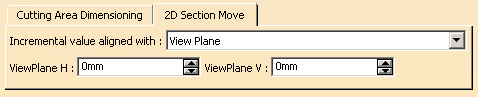
-
Select the 2D Section Move
tab.
This list contains all the features contained in the 2D-view section
node in the specification tree (GSD or sketcher, within groups or not,
wireframe or not, contained in view plane or not).
-
In the Incremental value aligned with list,
select the direction:
-
View Plane: allows you to move the
2D-view section elements along the visualization plane.
By default, this option is selected.
Note: If you are working with a 3D support, you can move the 2D-view
section along the 3D grid.
The default primary spacing of Work On Support 3D grid is 100mm for
each direction.
-
Intersection Cut Direction: allows you to
move the 2D-view section along the direction normal to cutting
plane.
You can switch from Intersection Cut Direction to
View Plane and vice-versa by double-clicking the manipulators.
-
In the ViewPlane H and
ViewPlane V
boxes, specify the values to define the location of manipulators.
-
Click OK.
The 2D-view section is moved.
|
|
|
|
|
|
Define the Section as the In Work Object
|
|
|
You can define a the 2D-view section as the In Work Object by selecting
appropriate mode. |
|
|
-
Click Define a Section as the In Work Object
in the Sections Management toolbar.
The Define In Work Section
dialog box appears.
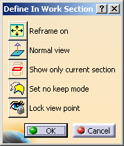
-
Click Reframe on
 to reframe the view and display the
section elements contained in a selected group. to reframe the view and display the
section elements contained in a selected group.
For further information, refer to Infrastructure User's Guide: Viewing
Objects: Reframing On an Object.
-
Click Normal View
 to display the cutting plane parallel
to the screen. to display the cutting plane parallel
to the screen.
For further information, refer to Infrastructure User's Guide:
Viewing Objects: Snapping the Viewpoint.
-
Click Show only current section
 to hide all the elements
from the 3D area except those of the selected section group. to hide all the elements
from the 3D area except those of the selected section group.
For further information, refer to Part Design User's Guide: Associating
Bodies: About Boolean Operations.
-
Click Set no keep mode
 to change the mode to
No Keep and
not retain an element on which you are performing an operation.
to change the mode to
No Keep and
not retain an element on which you are performing an operation.
For further information, refer to
Keeping the Initial Element.
-
Click Lock view point
 to lock or unlock the orientation
of the viewing vector. If it is activated, the viewing vector is locked
perpendicularly to the section plane. to lock or unlock the orientation
of the viewing vector. If it is activated, the viewing vector is locked
perpendicularly to the section plane.
For further information, refer to
Managing the Background Visualization.
-
Click OK to apply the current options.
|
|
|
For more information about 2D-view section, refer to
More about 2D-View Sections. |
|
|
|