There are a few things that you need to know when creating 2D-view sections.
|
About Nodes in the Specification Tree
- The Cut elements node contains the result of an
intersection operation performed on the group's geometries with the
section plane, as well as a join operation performed on this result
to unite non-connex wireframes.
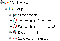
An additional Section join node is added under the Cut elements node. This node contains the result of a join operation performed on the point geometries resulting from an intersection operation performed on the group's geometries with the section plane. - The Section transformation node represents the
isometric transformation applied to the cut elements which are
contained in the intersection plane in order to replicate and
visualize these elements in the visualization plane.
An additional Section transformation node is added under the Group node in the specification tree. This node contains the isometric transformation of the new section join feature. - The Section join node is a join operation performed on the result of the section transformation and additional geometry added via the sketch edition in order to unite non-connex wireframes.
- The 2D-view thickness node contains the result of the optional corner and thickness operations performed on the elements of the section join.
You can insert your own GSD features in the 2D-view section under the 2D-view section node.
The visualization plane acts as a support plane for the wireframe elements added under the 2D-view section node.
Positioning of the View Plane Elements
The rectangular zone displayed on the plane chosen as the cutting plane is created when selecting the first element to be sectioned. The default size of this rectangle is chosen to loosely fit around all selected elements. Manipulators appear on the borders of this zone in the 3D area to modify its size. Changing its size restricts the portion of the section plane used to generate the wireframe elements contained in the Cut elements node.
As a consequence:
- These wireframe elements will no longer be the intersection of the whole cutting plane with the selected geometries but the intersection of the filled rectangle with the geometries.
- A connex intersection wireframe may become non-connex as a result of section plane delimitation.
- Some computed corners may be removed as a result of section plane
delimitation.
If the selected cutting plane is not an infinite plane but a bounded planar surface, delimiting manipulators are still usable. The original intersecting element is the bounded surface selected as the cutting plane and rectangular delimiters have no influence. Once manipulators are moved, the intersecting element becomes the rectangular zone influenced by the manipulators, and the boundaries of the original surfaces selected as cutting plane have no influence.
If the View and Intersection Planes are not Parallel
If this axis intersects the cutting zone rectangle, a rotation of the intersection wireframe elements around this axis is performed to place them in the view plane.
If this axis does not intersect the cutting zone rectangle, an axis parallel to this computed axis (which is also in the section plane and closer to the cutting zone) is used to perform the rotation of the intersection wireframe from section plane to view plane.
If the View and Intersection Planes are Parallel
A translation perpendicular to the section plane is
performed to place the intersection wireframe from the section plane to
the view plane.
If a Work on Support 3D exists and the chosen view plane is one of its
planes, it has an influence on the default positioning of the geometry
in the view plane: the plane from the Work on Support 3D grid closest to
the intersection wireframe geometry is chosen, an axis is defined by
intersecting this plane with the section plane, a rotation of the
wireframe geometry is performed around this axis, finally a translation
is performed from the Work on Support 3D plane to the originally picked
view plane.
![]()